Hi, I wanted to update about my own experience:
As I said in the previous post, I was able to get a Teensi 3.5: my friend actually had one and he agreed to sell it to me. So I contacted Citabria who was kind enough to help me flash my card. I used the instructions found here :
http://www.atariprotos.com/othersystems/sorcerer/misc/tapesim.htm
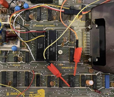
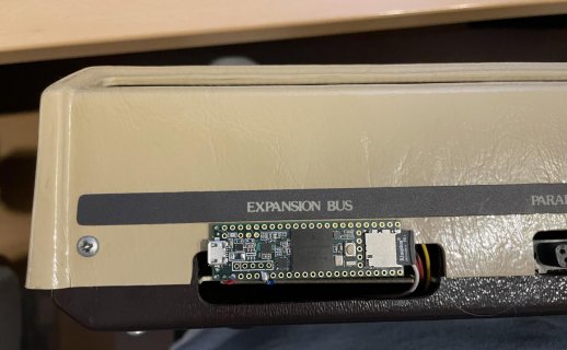
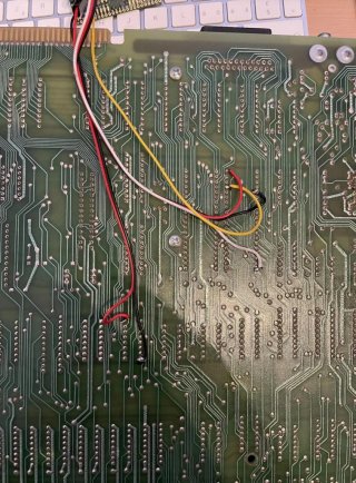
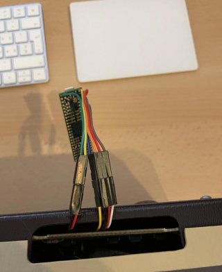
As I have an Exidy II, I had to take the signals directly on the controller. Instead of using test clips as described in the instructions, I opted for a solder under the motherboard. I then routed the Dupont cables to the expansion port and created a connector that allows me to unplug the Teensy in one step if I need to reprogram it. I attached it to the back with a double-sided tape to allow access to the SD card. It's non desctructive and visually it's ok.
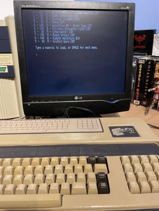
Everything works as expected. At first I had no software listed, then I realized that I needed to have a directory named Exidy at the root of the SD card, and that I should not put the files directly at the root.


