Hi forum,
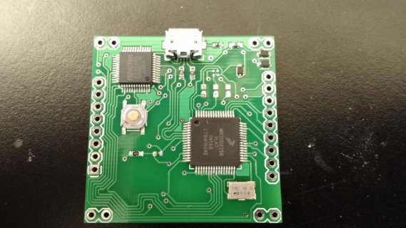
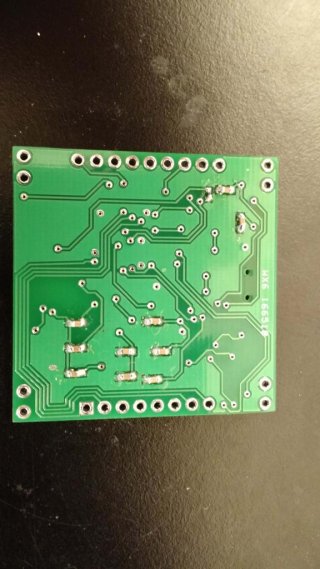
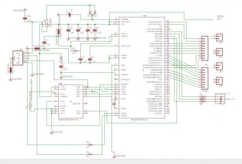
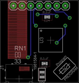
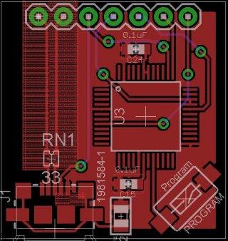
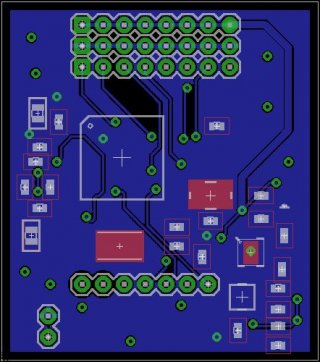
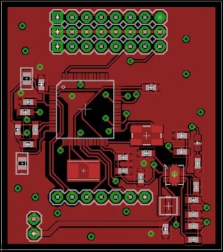
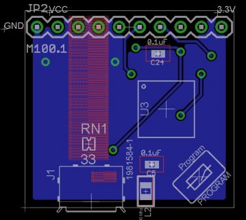
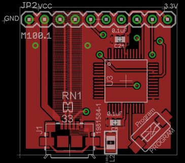
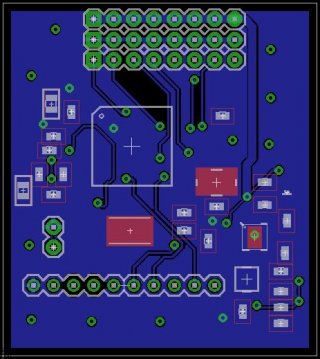
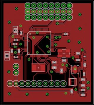
In an attempt to start developing in Cortex-M4, I've been working on trying to make a Teensy clone using Paul's MINI54 bootloader chip and the Teensy's MK20. This custom PCB is a square and loose rendition of the original. I assembled the components first using solder paste, and then used an iron and some wick to get rid of the excess bridges on the two main IC's. I've attached images of the board in this post.
At first, I plugged it into my machine and loaded a simple blink sketch to test if it would load code. It was unresponsive and the Teensy loader did not show up. I then reworked the pins manually by chasing solder across the pins to make sure that they were all well connected. Afterwards I plugged the Teensy back into my USB port, and it loaded the code! The Teensy loader showed up, I pressed the reset button, and the loader displayed "Reboot OK".
However, when I went back to test with a multimeter for whether the broken out GPIO were actually working with the blink sketch, they were either floating or completely 0V. Pins 14, 15, 16, 17, 20, 21, 22, 23 were broken out and tested with the blink sketches, with no signs of life. Another thing I noticed when I went back to the IDE, is that the USB port with a specific number was never picked up. It is as if the code was "loaded" in software, but not physically loaded into hardware. The loader confirms that the reboot is OK, but the Teensy itself is not functioning as if has been programmed. What accounts for the software saying that the code is loaded in the Arduino IDE with Teensy loader but the custom PCB itself not functioning?
This is my test code:
void setup() {
pinMode(13, OUTPUT);
pinMode(14, OUTPUT);
pinMode(15, OUTPUT);
pinMode(16, OUTPUT);
pinMode(17, OUTPUT);
pinMode(20, OUTPUT);
pinMode(21, OUTPUT);
pinMode(22, OUTPUT);
pinMode(23, OUTPUT);
}
void loop() {
digitalWrite(13, HIGH);
digitalWrite(14, HIGH);
digitalWrite(15, HIGH);
digitalWrite(16, HIGH);
digitalWrite(17, HIGH);
digitalWrite(20, HIGH);
digitalWrite(21, HIGH);
digitalWrite(22, HIGH);
digitalWrite(23, HIGH);
delay(2000);
digitalWrite(13, LOW);
digitalWrite(14, LOW);
digitalWrite(15, LOW);
digitalWrite(16, LOW);
digitalWrite(17, LOW);
digitalWrite(20, LOW);
digitalWrite(21, LOW);
digitalWrite(22, LOW);
digitalWrite(23, LOW);
delay(2000);
}
Assuming perfect assembly, my list of possible reasons is:
My understanding is that the USB connects directly to the Cortex-M4, which communicates with the bootloader to then overwrite the M4 so that it can accept the USB data. In this case, our problem suggests that there would be something wrong with the M4 or its circuitry rather than the bootloaders. A non-functioning M4 also offers an explanation as to why no USB port was detected on the Arduino IDE end. What are your thoughts?
Please let me know if I should provide any further materials if that would help out.
Your input means a lot. Thanks very much for all of your time!
In an attempt to start developing in Cortex-M4, I've been working on trying to make a Teensy clone using Paul's MINI54 bootloader chip and the Teensy's MK20. This custom PCB is a square and loose rendition of the original. I assembled the components first using solder paste, and then used an iron and some wick to get rid of the excess bridges on the two main IC's. I've attached images of the board in this post.
At first, I plugged it into my machine and loaded a simple blink sketch to test if it would load code. It was unresponsive and the Teensy loader did not show up. I then reworked the pins manually by chasing solder across the pins to make sure that they were all well connected. Afterwards I plugged the Teensy back into my USB port, and it loaded the code! The Teensy loader showed up, I pressed the reset button, and the loader displayed "Reboot OK".
However, when I went back to test with a multimeter for whether the broken out GPIO were actually working with the blink sketch, they were either floating or completely 0V. Pins 14, 15, 16, 17, 20, 21, 22, 23 were broken out and tested with the blink sketches, with no signs of life. Another thing I noticed when I went back to the IDE, is that the USB port with a specific number was never picked up. It is as if the code was "loaded" in software, but not physically loaded into hardware. The loader confirms that the reboot is OK, but the Teensy itself is not functioning as if has been programmed. What accounts for the software saying that the code is loaded in the Arduino IDE with Teensy loader but the custom PCB itself not functioning?
This is my test code:
void setup() {
pinMode(13, OUTPUT);
pinMode(14, OUTPUT);
pinMode(15, OUTPUT);
pinMode(16, OUTPUT);
pinMode(17, OUTPUT);
pinMode(20, OUTPUT);
pinMode(21, OUTPUT);
pinMode(22, OUTPUT);
pinMode(23, OUTPUT);
}
void loop() {
digitalWrite(13, HIGH);
digitalWrite(14, HIGH);
digitalWrite(15, HIGH);
digitalWrite(16, HIGH);
digitalWrite(17, HIGH);
digitalWrite(20, HIGH);
digitalWrite(21, HIGH);
digitalWrite(22, HIGH);
digitalWrite(23, HIGH);
delay(2000);
digitalWrite(13, LOW);
digitalWrite(14, LOW);
digitalWrite(15, LOW);
digitalWrite(16, LOW);
digitalWrite(17, LOW);
digitalWrite(20, LOW);
digitalWrite(21, LOW);
digitalWrite(22, LOW);
digitalWrite(23, LOW);
delay(2000);
}
Assuming perfect assembly, my list of possible reasons is:
- too much heat with rework
- faulty design
My understanding is that the USB connects directly to the Cortex-M4, which communicates with the bootloader to then overwrite the M4 so that it can accept the USB data. In this case, our problem suggests that there would be something wrong with the M4 or its circuitry rather than the bootloaders. A non-functioning M4 also offers an explanation as to why no USB port was detected on the Arduino IDE end. What are your thoughts?
Please let me know if I should provide any further materials if that would help out.
Your input means a lot. Thanks very much for all of your time!
Attachments
Last edited:


