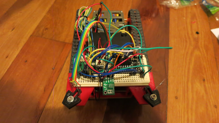
This rainbow mess of wires is my current T3 project:

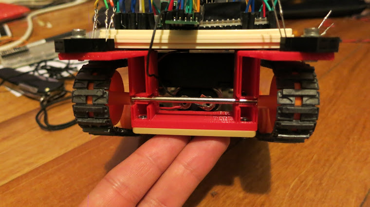
Initialy I had problems with the reversing track coming off the wheels when doing full speed turns on grippy surfaces, the tracks were too loose, so I printed a new front axle holder with two hex screws which push agansed the front axle and tightening the tracks. you can see the hex screw in the side pic:

front view:

I love my reprap prusa. soo useful. going to have to redesign and print this again for more places to screw sensors and stuff. but that's easy.
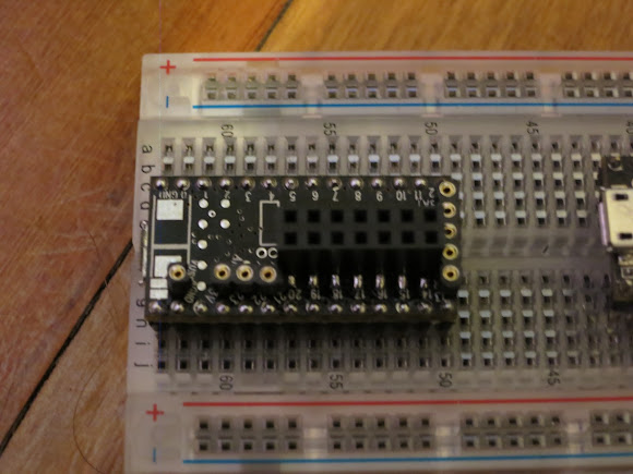
I soldered pins on the 'top' side of the T3, and some female headers on the 'bottom' giving me easy breadboard wire access to all the extra digital and analog pads:

this sort of worked, till I realized that although I'd put an oogoo spacer between the t3 and the pins to give the usb socket a bit more room between the breadboard and the t3, I still didn't quite have room for the usb plug to fit...
might cut out a small chunk of the breadboard to fix that little problem.
overall the robot is mostly sort of working well, it goes around and around in circles awesomely.
getting it going straight on a compass bearing is proving to be a little bit of a problem, it sometimes gets it right, but will often just spin in circles looking for the heading. I need to mess with it some more while plugged into laptop and read the serial out (I swear, half my code is Serial.print()).
I've found a fair number of mathy type bugs in my code already, but it's still not quite there yet.
I've got it so that I'm storing my desired heading and desired throttle with static vars. then the drive() function checks the desired_throttle and desired_heading functions, gets the current heading, compairs the current and desired headings, figures out how much it can throw the left and right throttle... maybe I should just post a snippet of code instead of trying to explain.
as you can see, lots of serial.prints in my code at the moment. and this is just one function.
first time I've really done anything from scratch in c. little bit of a learning curve. fun though.
might post the whole thing somewhere maybe.
other info:
compass: pololu MinIMU-9 v2
motor driver: pololu TB6612FNG
T3 power: 2xAA with a Pololu 5V Boost Regulator NCP1402.
motor power: 4xAA.
IR object sensors: qrb1114 (one of which I've managed to fry, oops.)
IR sensors is currently hooked up and coded so that if it detects something, it will stop, reverse a little, turn 90 deg from current heading, move forward, then continue with it's last desired heading and throttle orders. I might change that and use them on the tracks to detect actual speed/distance by detecting the gaps in the track. will have to print out a holder for that.
Initialy I had problems with the reversing track coming off the wheels when doing full speed turns on grippy surfaces, the tracks were too loose, so I printed a new front axle holder with two hex screws which push agansed the front axle and tightening the tracks. you can see the hex screw in the side pic:
front view:
I love my reprap prusa. soo useful. going to have to redesign and print this again for more places to screw sensors and stuff. but that's easy.
I soldered pins on the 'top' side of the T3, and some female headers on the 'bottom' giving me easy breadboard wire access to all the extra digital and analog pads:
this sort of worked, till I realized that although I'd put an oogoo spacer between the t3 and the pins to give the usb socket a bit more room between the breadboard and the t3, I still didn't quite have room for the usb plug to fit...
might cut out a small chunk of the breadboard to fix that little problem.
overall the robot is mostly sort of working well, it goes around and around in circles awesomely.
getting it going straight on a compass bearing is proving to be a little bit of a problem, it sometimes gets it right, but will often just spin in circles looking for the heading. I need to mess with it some more while plugged into laptop and read the serial out (I swear, half my code is Serial.print()).
I've found a fair number of mathy type bugs in my code already, but it's still not quite there yet.
I've got it so that I'm storing my desired heading and desired throttle with static vars. then the drive() function checks the desired_throttle and desired_heading functions, gets the current heading, compairs the current and desired headings, figures out how much it can throw the left and right throttle... maybe I should just post a snippet of code instead of trying to explain.
Code:
void drive()
{
    short desired_heading = getset_desired_heading('R', 0); //these two fuctions get or set the desired heading, 'R' since I'm reading them here, 'W' if I wanted to write or set them.
    short desired_throttle = getset_desired_throttle('R', 0);

    Serial.println("DRIVE");
    Serial.print("Desired Heading: ");
    Serial.println(desired_heading);
    Serial.print("Desired Throttle: ");
    Serial.println(desired_throttle);

    short current_heading = get_current_heading();
    short current_throttle = motor_state('R', 'B', 0); //another use of statics in a function, 'R' read 'B' returns both motors / 2. 'L' would be left 'R' would be right.
    Serial.print("Current Heading: ");
    Serial.println(current_heading);
    Serial.print("Current Throttle: ");
    Serial.println(current_throttle);

    short diff = degrees_difference(current_heading, desired_heading); //degrees_difference function returns the number of deg between current_heading and desired_heading, neg number if desired is 'left' of current.
    short aggro = (diff * 100) / 180; /aggressiveness of the turn.
    if (desired_throttle == 0) //if we're not moving foward or back, we need to use more juice to turn.
    {
        if (diff < 10 || diff > -10)
        {
            if (diff > 5 || diff < -5)
            {
                aggro = MIN_AGGRO;
            }
        }
    }

    Serial.print("Diff: ");
    Serial.println(diff);
    Serial.print("Aggro: ");
    Serial.println(aggro);

    //short left_power = motor_state('R', 'L', 0);
    //short rigt_power = motor_state('R', 'R', 0);
    short left_power = desired_throttle;
    short rigt_power = desired_throttle;
    short unused_left_pwr;
    short unused_rigt_pwr;
    short set_throttle_l;
    short set_throttle_r;

    if (diff < 0)
    {
        unused_left_pwr = 256 - left_power;
        unused_rigt_pwr = 256 - rigt_power;
        set_throttle_l = left_power - ((unused_left_pwr * aggro) / 100);
        set_throttle_r = rigt_power + ((unused_rigt_pwr * aggro) / 100);
    }
    else
    {
        unused_left_pwr = 256 - left_power;
        unused_rigt_pwr = 256 - rigt_power;
        set_throttle_l = left_power + ((unused_left_pwr * aggro) / 100);
        set_throttle_r = rigt_power - ((unused_rigt_pwr * aggro) / 100);
    }
    Serial.print("Unused_L: ");
    Serial.println(unused_left_pwr);
    Serial.print("Unused_R: ");
    Serial.println(unused_rigt_pwr);
    Serial.print("set_throttle_l: ");
    Serial.println(set_throttle_l);
    Serial.print("set_throttle_r: ");
    Serial.println(set_throttle_r);
    move(set_throttle_l, 'L');
    move(set_throttle_r, 'R');
}
as you can see, lots of serial.prints in my code at the moment. and this is just one function.
first time I've really done anything from scratch in c. little bit of a learning curve. fun though.
might post the whole thing somewhere maybe.
other info:
compass: pololu MinIMU-9 v2
motor driver: pololu TB6612FNG
T3 power: 2xAA with a Pololu 5V Boost Regulator NCP1402.
motor power: 4xAA.
IR object sensors: qrb1114 (one of which I've managed to fry, oops.)
IR sensors is currently hooked up and coded so that if it detects something, it will stop, reverse a little, turn 90 deg from current heading, move forward, then continue with it's last desired heading and throttle orders. I might change that and use them on the tracks to detect actual speed/distance by detecting the gaps in the track. will have to print out a holder for that.
Last edited:

