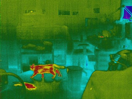
manicksan
Well-known member
It's time to share my latest project
https://github.com/manicken/ThermographicCamera
This started with that I wanted to check the house for heat loss,
but also be able to check electrical things for pre-failure,
and bought some MLX90614 to make a sweep-scan
with two servos, but that method is very slow and the used servos was unreliable
Meanwhile I was thinking to use better servos/(maybe stepper motors),
that project was postponed.
But then I saw this thread
https://forum.pjrc.com/threads/66816-MLX90640-Thermal-Camera-and-a-Teensy-4-0
and realized that MLX90640 was cheap, and after a lot of thinkin I did finally buy that sensor
found a Swedish site that did have them (for almost the same price as from mouser+shipping+import fees)
https://hitechchain.se/
Now with the new sensor + a ST7789 (1.3" 240x240) that I already had.
I first did a Raspberry PI Pico + circuit python
as it already did exist a working example that was very basic
but it was as expected very slow (~1fps)
Did try Teensy 4.0 with the same example but ran into issues as described here
https://forum.pjrc.com/threads/59040-CircuitPython-on-Teensy-4!?p=302661&viewfull=1#post302661
Just to clarify I use VSCODE + Platform IO
(as I could not think of using Arduino IDE for anything else than extremely very basic stuff)
So began to look for examples and both the Adafruit MLX90640 and ST7789 libraries did have examples
and both worked flawless.
So it was mostly wasted time of using Python as it don't really make any sense to use it,
except for small pre-prototype projects just to test things out.
(but now I have at least tested Python on a microcontroller)
My resulting code was based on the Display example as I did think it was the mostly 'complicated' of the two.
After the join I did just use enlarged pixels without any interpolation,
could do linear interpolation but do not like how that looks
and wanted to do bicubic interpolation (or at least try)
So after a lot of searching I did found example code @ Adafruit for another sensor
https://github.com/adafruit/Adafrui...les/thermal_cam_interpolate/interpolation.cpp
that could be run at ~7fps which is fairly impressive (the scale was then 1:7 as I am using a 240x240 TFT)
But then I was not really happy with the current color palette, think I found it here
https://github.com/adafruit/Adafrui...l_cam_interpolate/thermal_cam_interpolate.ino
and wanted to try some other
this was a fairly hard task as there is not really anywhere to find any (except for very blurry images)
but found finally this other project
https://github.com/maxritter/DIY-Thermocam
that did have 18 variants
but as they do take a lot of space (which makes the reprogramming slower)
also they do have different sizes and do not fit into the screen size
so each color palette would had to be remade to fit my particular screen size
My though was then to generate them from the base colors instead
then they would not take up so much space and could be generated at runtime
to fit any display size.
This lead to that I found code from FastLED (line:106)
https://github.com/FastLED/FastLED/blob/master/src/colorutils.cpp
also used the CRGB structure (or based my own upon it) from FastLED as it's easier to use.
Did beforehand do a own version of (fill_gradient_RGB),
but do now use the FastLED version as it generates smoother results
First I did try the code out in JavaScript (as it's very similar the conversion was no problem)
https://github.com/manicken/ThermographicCamera/tree/main/PaletteEditor
(not really a Palette Editor yet)
Where I also printed the color palettes from "DIY-Thermocam"
to see how they really looked like
(using 2d context on a canvas + createImageData + putImageData)
could then save these generated palettes as PNG:s
so I could use paint to extract the base colors
these was then put into the JavaScript program
so I could print both the "original" + the generated version
and the be able to finetune the percent's used to determine
how the generated palette would look like.
here is a example how two palettes could look like (JavaScript)
the same but in c++ struct
here they need to be all in one array,
and is using a another struct array to store the sizes and names
Here is the results in from the JavaScript program

Now I did think that the screen was to small 1.3"
And because the RoboRemo-app that I'm using for different projects
can receive and show Images in a so called Image-object
and do work together with USB OTG CDC.
First I did think it would be slow, but wanted to try it anyway
but after I did try it the first time it worked perfect
at least receiving 224x168(24bit) images
then I also put in some buttons to direct-select the current color palette
+ one image to show the current color palette
(updated only when the color palette is changed)
+ three textboxes to show the temperatures
here is the result
But I did also wanted to have this size "standalone"
so I bough a Olimex mod-lcd2.8rtp display (320x240 2.8" ILI9341+AR1021)
(it also have touch so I can make a settings screen in the future)
changing the color palette with two buttons at the moment
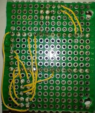
(in the current box they are no implemented yet, did exist on the breadboard)
This bigger display have a bigger resolution so now the framerate is down to ~5fps
(which is maybe not a big issue)
but as the MLX work at 1MHz I2C,
there is much time wasted just by waiting for it to complete the reads.
Then I was thinking it could do the Interpolation routine while waiting
To solve this I wanted to use TeensyThreads that run in "Cooperative multitasking"
"preemptive" did not work as it's hard to set the "time-slices" right.
Cooperative also is much better while sharing resources/variables
But do require yield in loops so that the different tasks allow to run.
I'm "overloading" the yield to
which used a function pointer callback that is set after all threads has been started
this ensure that there is threads to switch to? (had a problem with it enabled direct at startup)
First the the threading did not work,
but after a lot of tinkering and finally I did see what parameters the teensy threads have,
the I was thinking that it did have something to do with the stack size
and after setting it to 2kbyte it started to work a little, @4kbyte it worked flawless but was slower than the unthreaded version
After printing the used stack size I could see that the MLX read thread used a lot of memory,
and because it actually uses dynamically allocated memory to read the raw data this would then be copied onto the stack at task switch
(which takes a lot of time), so after changing all bigger arrays to static both the used stack size and the speed improved.
then It did work much faster ~7fps just as I wanted.
The resulted images now however is still a bit noisy
and did try Gaussian Interpolation from
http://blog.dzl.dk/2019/06/08/compact-gaussian-interpolation-for-small-displays/
+ my own tryout that work like this:
1. sensor 32x24 pixels "Gaussian interpolation" to 64x48
2. Bicubic interpolation from 64x48 to 160x120
3. Bicubic interpolation from 160x120 to 32x24 (maybe unnecessary to run Bicubic here, but easiest at the moment)
4. Bicubic interpolation from 32x24 to 288x208
that above decrease the noise but I did was still not really happy with it
The current version now uses a average method,
which uses a kind of circular buffer to store the latest read values
(up to 32 hardcoded, can be changed by a serial command)
this makes the update more smooth (faded)
than by just reading a lot of frames and then just print the average out
I have upgraded the "Tool" to receive and show images in a 'Node'
It uses the "Web Serial API" to receive the raw images in the "Roboremo-format".
This makes the "Remote Control (streaming)"-development faster
as otherwise it needs to be disconnected from my computer to the mobile.
here is a video showing how it looks like
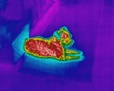
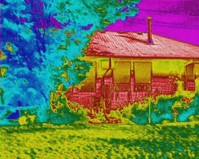
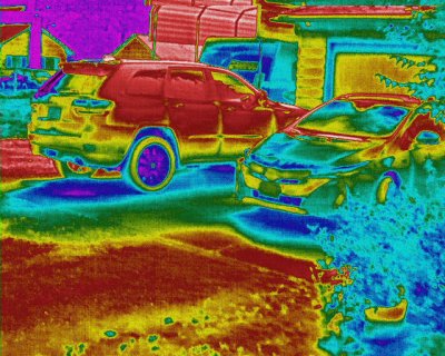
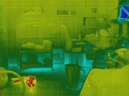
here is some pictures
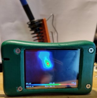
Is built into a recycled box from old test-equipment for old mobiles (sony ericsson)
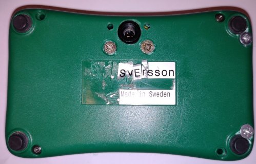
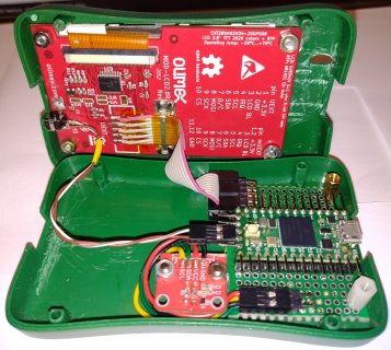
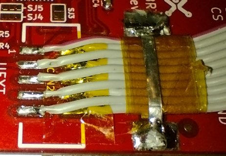
Here the wires are soldered direct onto the display
this makes some extra space that can be used for a future built in Li-Ion battery + TP4056 charger
currently powered by a external powerbank which is bulky
thermal camera "local" (standalone mode)
https://www.youtube.com/watch?v=3VbFxfoDFB8
(did have to change it into a url as I could not include more that 2 videos)
Future TODO:
* Buttons to change the color palette
* Built in Li-Ion + charger
* Touch GUI
* Maybe upgrade to Flir Lepton 3.5
(as it's have much better resolution)
and come with a fair price
at least if I make the breakout board myself
https://github.com/manicken/ThermographicCamera
This started with that I wanted to check the house for heat loss,
but also be able to check electrical things for pre-failure,
and bought some MLX90614 to make a sweep-scan
with two servos, but that method is very slow and the used servos was unreliable
Meanwhile I was thinking to use better servos/(maybe stepper motors),
that project was postponed.
But then I saw this thread
https://forum.pjrc.com/threads/66816-MLX90640-Thermal-Camera-and-a-Teensy-4-0
and realized that MLX90640 was cheap, and after a lot of thinkin I did finally buy that sensor
found a Swedish site that did have them (for almost the same price as from mouser+shipping+import fees)
https://hitechchain.se/
Now with the new sensor + a ST7789 (1.3" 240x240) that I already had.
I first did a Raspberry PI Pico + circuit python
as it already did exist a working example that was very basic
but it was as expected very slow (~1fps)
Did try Teensy 4.0 with the same example but ran into issues as described here
https://forum.pjrc.com/threads/59040-CircuitPython-on-Teensy-4!?p=302661&viewfull=1#post302661
Just to clarify I use VSCODE + Platform IO
(as I could not think of using Arduino IDE for anything else than extremely very basic stuff)
So began to look for examples and both the Adafruit MLX90640 and ST7789 libraries did have examples
and both worked flawless.
So it was mostly wasted time of using Python as it don't really make any sense to use it,
except for small pre-prototype projects just to test things out.
(but now I have at least tested Python on a microcontroller)
My resulting code was based on the Display example as I did think it was the mostly 'complicated' of the two.
After the join I did just use enlarged pixels without any interpolation,
could do linear interpolation but do not like how that looks
and wanted to do bicubic interpolation (or at least try)
So after a lot of searching I did found example code @ Adafruit for another sensor
https://github.com/adafruit/Adafrui...les/thermal_cam_interpolate/interpolation.cpp
that could be run at ~7fps which is fairly impressive (the scale was then 1:7 as I am using a 240x240 TFT)
But then I was not really happy with the current color palette, think I found it here
https://github.com/adafruit/Adafrui...l_cam_interpolate/thermal_cam_interpolate.ino
and wanted to try some other
this was a fairly hard task as there is not really anywhere to find any (except for very blurry images)
but found finally this other project
https://github.com/maxritter/DIY-Thermocam
that did have 18 variants
but as they do take a lot of space (which makes the reprogramming slower)
also they do have different sizes and do not fit into the screen size
so each color palette would had to be remade to fit my particular screen size
My though was then to generate them from the base colors instead
then they would not take up so much space and could be generated at runtime
to fit any display size.
This lead to that I found code from FastLED (line:106)
https://github.com/FastLED/FastLED/blob/master/src/colorutils.cpp
also used the CRGB structure (or based my own upon it) from FastLED as it's easier to use.
Did beforehand do a own version of (fill_gradient_RGB),
but do now use the FastLED version as it generates smoother results
First I did try the code out in JavaScript (as it's very similar the conversion was no problem)
https://github.com/manicken/ThermographicCamera/tree/main/PaletteEditor
(not really a Palette Editor yet)
Where I also printed the color palettes from "DIY-Thermocam"
to see how they really looked like
(using 2d context on a canvas + createImageData + putImageData)
could then save these generated palettes as PNG:s
so I could use paint to extract the base colors
these was then put into the JavaScript program
so I could print both the "original" + the generated version
and the be able to finetune the percent's used to determine
how the generated palette would look like.
here is a example how two palettes could look like (JavaScript)
Code:
var gps = {
    IronBow:[
        {p:0, c:new CRGB(0,0,0)},        // black
        {p:10, c:new CRGB(32,0,140)},    // dark blue
        {p:35, c:new CRGB(204,0,119)},   // magenta red
        {p:70, c:new CRGB(255,165,0)},   // orange
        {p:85, c:new CRGB(255,215,0)},   // gold
        {p:100, c:new CRGB(255,255,255)} // white
    ],
    RainBow:[
        {p:0,     c:new CRGB(0,0,0)},      // white
        {p:100/6, c:new CRGB(0,0,255)},    // blue
        {p:200/6, c:new CRGB(0,255,255)},  // cyan
        {p:300/6, c:new CRGB(0,255,0)},    // green
        {p:400/6, c:new CRGB(255,255,0)},  // yellow
        {p:500/6, c:new CRGB(255,0,0)},    // red
        {p:100,   c:new CRGB(255,255,255)} // white
    ],
};here they need to be all in one array,
and is using a another struct array to store the sizes and names
Code:
const struct GradientPaletteDef Def[] = {

        {"Iron Bow",6},        // 0
        {"Rain Bow 0",9}      // 1
}
const struct GradientPaletteItem Data[] = {
        // IronBow // 6
        {0,     {0,0,0}}, // black
        {10.0f, {32,0,140}}, // dark blue
        {35.0f, {204,0,119}}, //magenta red
        {70.0f, {255,165,0}}, // orange
        {85.0f, {255,215,0}}, // gold
        {100.0f,{255,255,255}},  // white
        // RainBow0 // 7
        {0,     {0,0,0}}, // black
        {100/6, {0,0,255}}, // blue
        {190/6, {0,255,255}}, // cyan
        {220/6, {0,255,255}}, // cyan
        {300/6, {0,255,0}}, // green
        {390/6, {255,255,0}}, // yellow
        {410/6, {255,255,0}}, // yellow
        {500/6, {255,0,0}}, // red
        {100,   {255,255,255}} // white
}
Here is the results in from the JavaScript program

Now I did think that the screen was to small 1.3"
And because the RoboRemo-app that I'm using for different projects
can receive and show Images in a so called Image-object
and do work together with USB OTG CDC.
First I did think it would be slow, but wanted to try it anyway
but after I did try it the first time it worked perfect
at least receiving 224x168(24bit) images
then I also put in some buttons to direct-select the current color palette
+ one image to show the current color palette
(updated only when the color palette is changed)
+ three textboxes to show the temperatures
here is the result
But I did also wanted to have this size "standalone"
so I bough a Olimex mod-lcd2.8rtp display (320x240 2.8" ILI9341+AR1021)
(it also have touch so I can make a settings screen in the future)
changing the color palette with two buttons at the moment
(in the current box they are no implemented yet, did exist on the breadboard)
This bigger display have a bigger resolution so now the framerate is down to ~5fps
(which is maybe not a big issue)
but as the MLX work at 1MHz I2C,
there is much time wasted just by waiting for it to complete the reads.
Then I was thinking it could do the Interpolation routine while waiting
To solve this I wanted to use TeensyThreads that run in "Cooperative multitasking"
"preemptive" did not work as it's hard to set the "time-slices" right.
Cooperative also is much better while sharing resources/variables
But do require yield in loops so that the different tasks allow to run.
I'm "overloading" the yield to
Code:
void yield()
{
    if (yieldCB != NULL)
        yieldCB();
}this ensure that there is threads to switch to? (had a problem with it enabled direct at startup)
First the the threading did not work,
but after a lot of tinkering and finally I did see what parameters the teensy threads have,
the I was thinking that it did have something to do with the stack size
and after setting it to 2kbyte it started to work a little, @4kbyte it worked flawless but was slower than the unthreaded version
After printing the used stack size I could see that the MLX read thread used a lot of memory,
and because it actually uses dynamically allocated memory to read the raw data this would then be copied onto the stack at task switch
(which takes a lot of time), so after changing all bigger arrays to static both the used stack size and the speed improved.
then It did work much faster ~7fps just as I wanted.
The resulted images now however is still a bit noisy
and did try Gaussian Interpolation from
http://blog.dzl.dk/2019/06/08/compact-gaussian-interpolation-for-small-displays/
+ my own tryout that work like this:
1. sensor 32x24 pixels "Gaussian interpolation" to 64x48
2. Bicubic interpolation from 64x48 to 160x120
3. Bicubic interpolation from 160x120 to 32x24 (maybe unnecessary to run Bicubic here, but easiest at the moment)
4. Bicubic interpolation from 32x24 to 288x208
that above decrease the noise but I did was still not really happy with it
The current version now uses a average method,
which uses a kind of circular buffer to store the latest read values
(up to 32 hardcoded, can be changed by a serial command)
this makes the update more smooth (faded)
than by just reading a lot of frames and then just print the average out
I have upgraded the "Tool" to receive and show images in a 'Node'
It uses the "Web Serial API" to receive the raw images in the "Roboremo-format".
This makes the "Remote Control (streaming)"-development faster
as otherwise it needs to be disconnected from my computer to the mobile.
here is a video showing how it looks like
here is some pictures

Is built into a recycled box from old test-equipment for old mobiles (sony ericsson)


Here the wires are soldered direct onto the display
this makes some extra space that can be used for a future built in Li-Ion battery + TP4056 charger
currently powered by a external powerbank which is bulky


thermal camera "local" (standalone mode)
https://www.youtube.com/watch?v=3VbFxfoDFB8
(did have to change it into a url as I could not include more that 2 videos)
Future TODO:
* Buttons to change the color palette
* Built in Li-Ion + charger
* Touch GUI
* Maybe upgrade to Flir Lepton 3.5
(as it's have much better resolution)
and come with a fair price
at least if I make the breakout board myself
Last edited:


