KurtE
Senior Member+
- Joined
- Last seen
- Viewing latest content
- Messages
- 12,085
- Reaction score
- 158
Latest activity Postings About
-
-
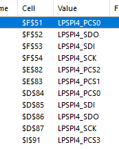
 KurtE replied to the thread Call to arms | Teensy + SDRAM = true.Note: I edited the previous post to show the SerialX objects that the DB4.5 plus the 6 pins suggested to be added (all of the missing AD_B1_xx pins). For Arduino SPI objects: SPI is setup to use the LPSPI4 object: With the pins as mentioned...
 -
-
KurtE replied to the thread USBHost_t36 slow reception of incoming data.Sorry, yes the read code was implemented with KISS to get it up and running. I meant to at some point potentially go back and do the memcpy version. At the time we were chasing other bugs and so did not add the complexity of dealing with the...
-
KurtE replied to the thread Call to arms | Teensy + SDRAM = true.I just pushed up a slightly updated Excel document, where I moved the AD_B1_03 pin down into the new pin area at the end of the list. Also fixed some of the color coding, but I know that some more work on this can be done. I already fixed a...
-
-
KurtE replied to the thread USBHost_t36 slow reception of incoming data.Have you tried using the bigbuffer version of the Serial objects? And see if that helps? For higher speeds, we might need to update the code to have more than two USB buffers at a time. For example, the RAWHID code was updated for 4 RX and...
-
KurtE replied to the thread USBHost_t36 and FTDI device - so close!.You are right, that the bigbuffer was setup to handle USB High Speed devices, which typically have transfers of 512 bytes instead of 64 bytes, as well as higher speeds. the ,1 was a hack as by default it will only claim high speed serial...
-
KurtE replied to the thread T4 Pixel Pipeline Library.Thanks, There are a lot of great stuff shown in your video! At some point it will be interesting to play with some of these more advanced features!
-
The PXP can be very useful for some applications. A little over 3 years ago, I used it to manipulate images for a slide show app. The PXP made possible things like fade-in, fade-out, moving transitions, and Ken Burns effect (combination of...
-
KurtE replied to the thread T4 Pixel Pipeline Library.Thanks, will take a look. At this point, I think I will defer for now. If the main issue is simply to rotate by 90, 180, 270 with most of our displays, we can simply tell the display to set their rotation and the rest is taken care of. If I...
-
@KurtE the partial output buffers only work with the eLCDIF handshake. The only way to use this on a non SDRAM Teensy is to use one screen size source buffer and two partial destination buffers I was able to rotate a landscape frame generated...
-
@KurtE - @Rezo here is a working sketch using a OV5640 or OV2640. Tested with QVGA, QQVGA and 240x240 framesizes
-
KurtE replied to the thread T4 Pixel Pipeline Library.@mjs513 - glad you have it working! Will have to play with it some more. (All) But I am wondering how/where I might use it on a normal Teensy, where I don't have external memory and I am not using eLCD? That is are there examples on how one...
-
Have to swap the values for the OUT_LRC register - didn;t register (pardon the pun) that this was different than PXP_OUT_PS_LRC. PXP_OUT_LRC appears to set the display LRC, hence the need for: if(r == 0 || r == 2) {...
-
Got it !!! Found it by accident: solution: void pxp_rotation(int r) { if(!pxpStarted) { Serial.println("You forgot to start PXP, use 's' to start....."); } else { memset((uint8_t *)d_fb, 0, sizeof_d_fb); PXP_rotate_position(0)...
-
Will give it a try - but question on lrc/ulc - do these change with rotation
-
Thanks for joining the fray here. Right now I am using QVGA with a ILI9341 so using 2 full size buffers: DMAMEM uint16_t s_fb[320*240] __attribute__ ((aligned (64))); uint16_t d_fb[320*240] __attribute__ ((aligned (64))); Right now I have just...
-
KurtE replied to the thread Adding more memory to Serial (0) for larger buffers.Sorry, I don't believe that is possible. AFAIK - it is only implemented within HardwareSerial, (and maybe FlexIO Serial)... My guess is you can probably edit the source code, to allow for larger count of buffers: like usb_serial.c Where you...
-
KurtE replied to the thread T4 Pixel Pipeline Library.Sorry @mjs513, I am not much help on this one. I keep meaning to learn more about the PXP stuff. As there might be places it could come in handy. For example with the ILI9488_t3 code, we typically store the pixels in 16 bit 565 format, but the...
-
Made a little progress - but out image is always a square. Kind of giving up on rotations - ps it easier to set the display to do the rotation if thats all you are doing on an image - probably not good to do it with video unless display doesn't...
-
Here's the problem For Rotation 0 - seems to be working but image is not centering as specified in the writeRect function Rotation 1 - notice it draws it on the top have of the screen as what looks like a wrapped image: Rotation 2 - see...
-
Double row is possible, I hope that we can cut a few pins away to allow for simpler routing. And when you guys make the complete list of pins, you can not which pins should ideally have short traces, and I will abide to that. The many grounds...
-
Trying to figure out how PXP works but it is giving me a headache - I posted something on the PXP thread. Trying to figure out how scaling works to say downsize an image. But all in good time - examples are few and far in between
-
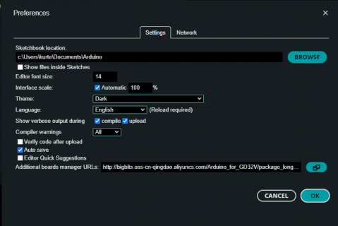
KurtE replied to the thread Teensy 4.1 function call order in setup() affects the flow of code.I would suggest, that if you have not already done so, see if the compiler is giving you any hints. That is make sure you have the option turned on to show all warnings. Notice the compiler warnings: All And rebuild the code. I don't remember...
-
-
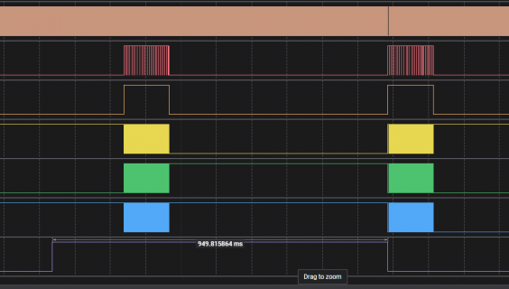
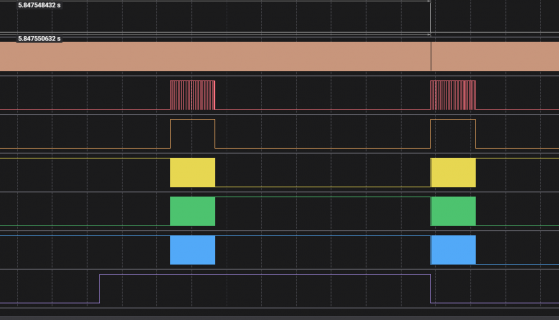
You don't need to use one of the parallel shifters, just use the one below your receive shifter (so likely either shifter 6 or 2) and configure it for match continuous mode, the same timer as the other shifter, PWIDTH=15 (16 bits) and INSRC=1. So...
-
@KurtE Been playing with your latest changes and testing on with the 2640 and 5640. With the 2640 jpeg seems to be problematic maybe will get a good image 1 in 10 times or so. With the Adafrut 5640 seems to be working like a charm - even able...
-
KurtE replied to the thread Teensy 4.1 function call order in setup() affects the flow of code.Sorry we only see a few bits and pieces of your code, so we can only throw darts and hopefully one will hit the mark. Can it be a memory issue? Yes That is for example maybe one or more things you call or do corrupts the memory. For example...
-
KurtE replied to the thread New Camera Library for Teensy Micromod/4.1.Question/Wondering: Currently with our JPEG input code, we are using some pretty primitive code to detect the end of the JPEG stream (0xff followed by 0xd9). That is we are working without DMA, and manually scan the new data coming in for this...
-
KurtE replied to the thread Teensy 4.1 function call order in setup() affects the flow of code.I am guessing along the same lines as Paul mentioned. That is maybe the values read in are not as expected and maybe something called after this point errored on these values. If it were me, I would print out the values returned from the EEPROM...
-
KurtE reacted to PaulStoffregen's post in the thread USB connection from D+ / D- pins with external supply with
 Like.
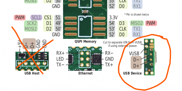
Earlier I believed you had cut a USB cable and soldered its wires directly to the pads on the bottom side of Teensy 4.1. I assumed that from words "not from a USB cable connected to the D+ / D- and GND pins". But in this photo, it is not a USB...
Like.
Earlier I believed you had cut a USB cable and soldered its wires directly to the pads on the bottom side of Teensy 4.1. I assumed that from words "not from a USB cable connected to the D+ / D- and GND pins". But in this photo, it is not a USB... -
KurtE reacted to PaulStoffregen's post in the thread USB connection from D+ / D- pins with external supply with Like.
When you edit usb.c, first try adding any simple syntax error. Then click Verify. Arduino IDE should notice the file changed and recompile. Seeing the syntax error quickly confirms Arduino really is recompiling the code and you really are...
-
KurtE replied to the thread USB connection from D+ / D- pins with external supply.Wondering if maybe your cabling and the like is screwing up the signals that are seen by the host, to detect that there is a device and if so, what speed should it communicate at ...
-
KurtE replied to the thread How to trigger interrupt on falling/rising edge of sent PWM signal?.You might want to look at the Arduino documentation for attachInterrupt: https://www.arduino.cc/reference/en/language/functions/external-interrupts/attachinterrupt/ const byte ledPin = 13; const byte interruptPin = A9; volatile byte state = LOW...
-
KurtE replied to the thread Outdated documentation on interrupts?.Yes this web page is way out of date! It is specific to AVR based boards like the old Teensy 2.x Not sure what you are trying to do, so hard to suggest solutions. For example the TIMER0 is specific to the processor you are using. I assume by...
-
KurtE replied to the thread New Camera Library for Teensy Micromod/4.1.Quick update on using the CSI setup to try to read in Jpeg images in from OV2640 and later OV5640 on Teensy 4.1. I tried several different ways to make it work within CSI subsystem. I was tried several different ways to turn off using their DMA...
-
-
There is always a chance that an MJPG frame could end up larger than an uncompressed frame, if the quality is turned up and the frame has lots of detail that can't be compressed (things like ocean waves and grassy lawns are typical causes).
-
KurtE replied to the thread Anti-spam effort in 2024 - Please report spam quickly when you see it.Wonder if you can do it by class of person? That way maybe some of us can for example edit the first post of certain threads, that for example keeps a summary of the state of some project...
-
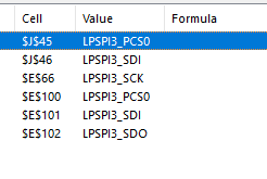
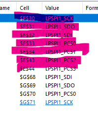
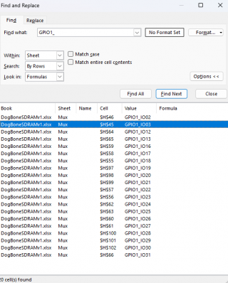
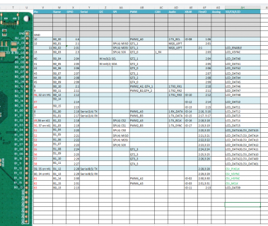
KurtE replied to the thread Call to arms | Teensy + SDRAM = true.Not sure if this would help or, not, but I tried to create a IO pin MUX page for the Dogbone document with I think most of the IO pins that are on the board. It shows the SDIO pins which were added on 4.5 board in different color... Those should...
-
KurtE replied to the thread New Camera Library for Teensy Micromod/4.1.Thanks @jmarsh and @mjs513 Quick note on the main CSI pins, (AD_B1_xx) pins, that are used on Teensy 4.1. They are also FlexIO pins but on FlexIO3, which does not have DMA, so we have not tried using it... But could especially, if we do it...
-
I haven't done it with CSI, I used FlexIO instead with a shifter register in match store mode to detect the ending sequence. It sounds like the same situation as with LCDIF: the reference doc says you can perform the DMA "manually" but gives no...
-
KurtE replied to the thread New Camera Library for Teensy Micromod/4.1.Wondering has anyone tried using the CSI subsystem without using their built in DMA? Two different ways, I might find it interesting: a) Reading in JPEG. Yesterday I was sort of able to get it to maybe read in one JPEG using DMA, I think I...
-
-
KurtE replied to the thread Call to arms | Teensy + SDRAM = true.I think which new pins could/should be added to support has been shown now in a few threads including: Question, what do you mean by complete? That is I have not seen what I would consider a complete one for DB4 or DB4.5. That is one that...
-
As some of you know I made a 4.5 (facelift) that adds USB-PD (USB Power Delivery up to 12V). And it also has SDCARD. Those are the only changes made (moved the boot button position as well), hence the word facelift. The USB Host port has sort of...
-
KurtE replied to the thread USB connection from D+ / D- pins with external supply.I could not tell from your description, if there is a common GND signal? That is does your USB GND connect to the Teensy? Edit: sounds like there is, but would double check... (I was thinking of a different thread....) But Pictures of your...
-
-
I received my 74LVC245 chips and had some fun wiring this rat's nest up: This took care of the bad image when loading from FLASHMEM. Both FLASHMEM and SDRAM are working using 8-bit DMA. The image is correct and repeatable at 20MHz. I only...
-
Was playing around jpegdec library and did a comparison of using PROGMEM vs SDRAM (running at 198Mhz) FLash TEST full sized decode in 28350 us half sized decode in 21260 us quarter sized decode in 7320 us eighth sized decode in 6104 us SDRAM...
-
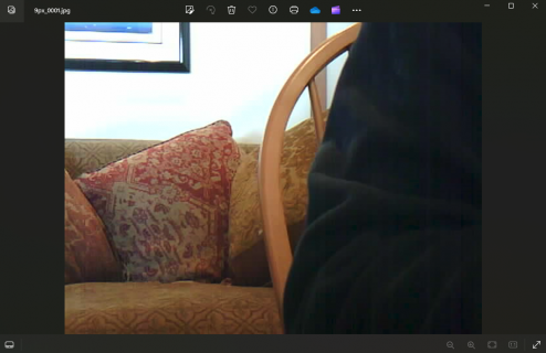
KurtE replied to the thread New Camera Library for Teensy Micromod/4.1.Quick updates on CSI code: I now have more of it working with T4.1 and CSI running in VGA size, with PSRAM for frame buffer. I have more of it working now. With the VGA sketch, using OV7675 camera PSRAM, where f command is working, as is m and...
-
-
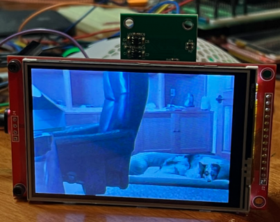
Have the SDRAM board wired up to the ER-TFT101-1 display. DMA is working on it as well as the MicroMod, sort of! This is the test sketch I am using modified to include SDRAM usage: #include "RA8876_t3.h" #include "SDRAM_t4.h" #include...
-
Merged: https://github.com/Defragster/EVKB_1060/blob/main/docs/DogBoneSDRAMv1.xlsx
-
KurtE replied to the thread Call to arms | Teensy + SDRAM = true.Sorry, I did not go all the way up on the SS to those pins... I have now... Exactly. Pushed up current version to fork of defragsters github project and issued PR https://github.com/Defragster/EVKB_1060/pull/1
-
KurtE replied to the thread Call to arms | Teensy + SDRAM = true.Thanks, @mjs513 (and others), I updated again the dogbone... excel document all of the LCD pins on the right hand side of the board were filled in. I think it should look like: Will send the document back to you and/or could try to do PR with...
-
-
@KurtE the dev board has all the eCLDIF pins exposed. Starting from B0_00 to B1_13 I believe. I posted here a few weeks back that I got it working on a 24 bit display with SDRAM.
-
-
Loading…
-
Loading…