wwatson
- Messages
- 965
- Reaction score
- 77
Latest activity Postings About
-
-
 wwatson replied to the thread Call to arms | Teensy + SDRAM = true.Well it's pretty much finished. Modified the SDRAM Dev board /RD signal to use manual pulse generation. Bus speeds are about the same as the T4.1:D The FlexIO /RD signal generation seems to have been the main issue for stability. It kind of makes...
 -
-
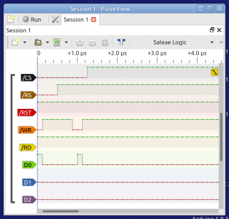
wwatson replied to the thread Call to arms | Teensy + SDRAM = true.Quick update: Dumped the FlexIO /RD generation and generated it manually with software. Both 8-bit and 16-bit reads are working consistently now with one /RD pulse per read instead of two or sometimes three. Tested with T41 and ER-TFTM101-1...
-
Quick update on using the CSI setup to try to read in Jpeg images in from OV2640 and later OV5640 on Teensy 4.1. I tried several different ways to make it work within CSI subsystem. I was tried several different ways to turn off using their DMA...
-
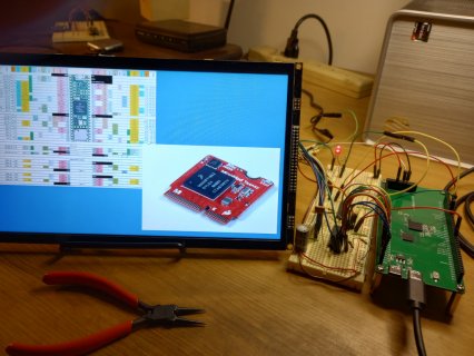
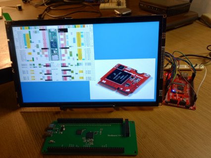
wwatson replied to the thread Call to arms | Teensy + SDRAM = true.I received my 74LVC245 chips and had some fun wiring this rat's nest up: This took care of the bad image when loading from FLASHMEM. Both FLASHMEM and SDRAM are working using 8-bit DMA. The image is correct and repeatable at 20MHz. I only...
-
-
Was playing around jpegdec library and did a comparison of using PROGMEM vs SDRAM (running at 198Mhz) FLash TEST full sized decode in 28350 us half sized decode in 21260 us quarter sized decode in 7320 us eighth sized decode in 6104 us SDRAM...
-
wwatson replied to the thread Call to arms | Teensy + SDRAM = true.I had not thought of that. What's interesting is it works fine from flash memory on the MicroMod and T41. So maybe there is a conflict somewhere. I could speed up the bus rate and see if that changes any thing... Edit: Went from 2MHz to 24MHZ...
-
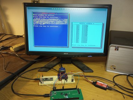
wwatson replied to the thread Call to arms | Teensy + SDRAM = true.Have the SDRAM board wired up to the ER-TFT101-1 display. DMA is working on it as well as the MicroMod, sort of! This is the test sketch I am using modified to include SDRAM usage: #include "RA8876_t3.h" #include "SDRAM_t4.h" #include...
-
-
wwatson replied to the thread Call to arms | Teensy + SDRAM = true.We finally have DMA working properly on the MicroMod and presumably the SDRAM Dev Board (not tested yet). My MicroMod quit while testing the 8080 mode for the ER-TFTM101-1 display. Had to reposition the MCU board in the connector. It's working...
-
-
wwatson reacted to mjs513's post in the thread New Camera Library for Teensy Micromod/4.1 with
 Like.
While @KurtE has been busy with CSI we also been playing with the OV5640 5MB camera which we got from Adrafruit: https://www.adafruit.com/product/5673 for the most part it was compatible with Flexio that we used for the OV2640 but of course lib...
Like.
While @KurtE has been busy with CSI we also been playing with the OV5640 5MB camera which we got from Adrafruit: https://www.adafruit.com/product/5673 for the most part it was compatible with Flexio that we used for the OV2640 but of course lib... -
Thought I would mention, I am currently playing with trying to add CSI support for this library, as the Teensy 4.1 has enough of the CSI pins exposed for 8-bit transfers, and the control signals. I am starting off with the OV7675 camera, and I...
-
wwatson replied to the thread Call to arms | Teensy + SDRAM = true.I think it might have more to do with the ER-TFTM101-1 display as I am using the same length wires as well. I do not have any other displays to test with...
-
wwatson replied to the thread Call to arms | Teensy + SDRAM = true.Update ER-TFTM1011-1 10.1" LCD is working on the T4.1, MicroMod and SDRAM Dev Board V4.0. All except MicroMod work with 8-bit and 16 bit bus configuration. The T4.1 is by far the most stable of all three. The SDRAM board and MicroMod are unstable...
-
If you are building a specific board for a specific purpose, I say have at it! IF you like hard coding it like: IOMUXC_SW_MUX_CTL_PAD_GPIO_AD_B1_13 = 0x4U; IOMUXC_CSI_DATA04_SELECT_INPUT = 0; IOMUXC_SW_PAD_CTL_PAD_GPIO_AD_B1_13 = 0x0U, go for...
-
A couple of questions and things I am playing with... With the 4.5 and SD adapter: guessing you used SDIO pins? (Same ones as defined for Micromod?) of if SPI which IO pins? CSI pins - I am in the process of integrating in some CSI support...
-
So I decided to make a facelift, adding SDCARD and USB-PD which supports the PD protocol up to 12V. There are pads to solder if you just want to use the second port as a pass through with 5V. Meaning, it will deliver the same 5V coming into the...
-
wwatson replied to the thread Call to arms | Teensy + SDRAM = true.I found an Arduino 8080 parallel IF used for the RA8875 (same 8080 interface as RA8876) that uses 74LV245's as buffers for the Due and possibly the Mega 2560 found here. I am going to order up some of these chips if I don't have any left and see...
-
wwatson replied to the thread Call to arms | Teensy + SDRAM = true.What length wires are you using between the MCU and the display boards? WIth 10cm wires I could not get past 20Mhz when testing With an LCD and Micromod mounted to the same pcb with 2cm traces we got 24/30Mhz working. I am using the same length...
-
wwatson replied to the thread Call to arms | Teensy + SDRAM = true.Thanks for the response. I wired up the dev board again and started testing with the baseline driver code I posted. It shows something is wrong in the dev board/MicroMod side of my code. No matter what I set the bus speed to loading the same...
-
-
wwatson replied to the thread Call to arms | Teensy + SDRAM = true.That's why I hope Rezo can go over the low level drivers I posted to make sure I am not missing something. I have a general idea of how FlexIO works but I might be missing some little details. Meanwhile I am wiring up the DevBoard again to test...
-
wwatson replied to the thread Call to arms | Teensy + SDRAM = true.I remember reading that. At this point I am not using the SDRAM at all with the display. It is strictly the traces between the 1062 MCU and the out side connectors of the board. Once that and DMA communications are solved then I can start testing...
-
wwatson replied to the thread Call to arms | Teensy + SDRAM = true.@Rezo Here is the FlexIO2 pin usage I am using: FlexIO2------- Dev Board-------- ER-TFTM101-1 Pin 2:00 -----------> B0_00 -----------> /WR ---> 05 2:01 -----------> B0_01 -----------> /RD ---> 06 2:02 -----------> B0_02 -----------> 2:03...
-
wwatson replied to the thread Call to arms | Teensy + SDRAM = true.16 bits... lcdRegWrite(RA8876_CCR);//01h #if defined(USE_8080_IF) if(BUS_WIDTH == 16) { lcdDataWrite(RA8876_PLL_ENABLE<<7|RA8876_WAIT_NO_MASK<<6|RA8876_KEY_SCAN_DISABLE<<5|RA8876_TFT_OUTPUT24<<3...
-
wwatson replied to the thread Call to arms | Teensy + SDRAM = true.Not having good results with the SDRAM board and RA8876 in 16-bit 8080 mode. It's very unstable results:( Been playing with delays with no predictable results even at 2MHz. If I switch to 8-bit mode all of the examples in the Ra8876LiteTeensy...
-
wwatson replied to the thread Flashing 4.1 code on a board with a 4.0 bootloader chip.Thanks @Rezo - Will set it up in the AM. Bedtime...
-
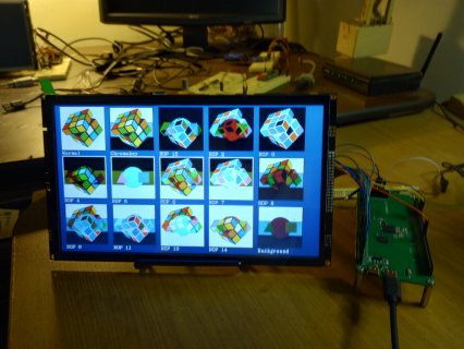
wwatson replied to the thread Call to arms | Teensy + SDRAM = true.Here is the SDRAM board and ER-TFTM101-1 TFT working in 8080 8-bit mode. It's a start:) Waiting on some info to try out 16-bit 8080 mode...
-
-
wwatson replied to the thread Flashing 4.1 code on a board with a 4.0 bootloader chip.Thanks - I do have the SDRAM board and TFT working in 8-bit mode now. Just fine tuning to see what kind of speed I can get...
-
wwatson replied to the thread Flashing 4.1 code on a board with a 4.0 bootloader chip.@Rezo - I see B0_13 is available on the SDRAM DEV board. It does not have a pin number associated with it. How would you setup B0_13 as FlexIO 2:13 without a pin number as being done like this: /* Basic pin setup */ pinMode(10, OUTPUT)...
-
wwatson replied to the thread Call to arms | Teensy + SDRAM = true.Just re-did it all and it's working :D Must have messed up on the wiring. Probably one off. It now works out of the box...
-
wwatson replied to the thread Call to arms | Teensy + SDRAM = true.Unless I missed something both B0_12 (35) and B0_13 (34) did not respond to a pin check with and LED connected to them. Just rechecked and they are not connected as well as pin B1_02 (36) and B1_03 (37). The only pin that is labeled as a T41 pin...
-
wwatson replied to the thread Call to arms | Teensy + SDRAM = true.Hi Defragster - I am using @jmarsh's SDRAM_EXTMEM library. I only had to modify one sketch that was setup for the T41. The rest of them work out of the box. The sketch that I modified was "flexio_vga.ino" which basically just changed the VSYNC...
-
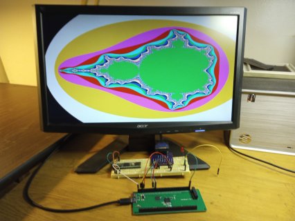
wwatson replied to the thread Call to arms | Teensy + SDRAM = true.@jmarsh - Tested the elcdif sketches. Impressive:D Did not realize the mandelbrot sketch was animated. Now to hook up the 10.1" LCD and test... EDIT: By the way the T41 on the breadboard is the first T41 I got from PJRC. It has the white...
-
-
wwatson replied to the thread Call to arms | Teensy + SDRAM = true.Thanks for the info and link above. I now have it working with external sdram. It seems to work ok up to 270MHz with a 1280x720 frame buffer. Excuse my shakey picture:) I still am not using double buffering like in your original sketch but it...
-
-
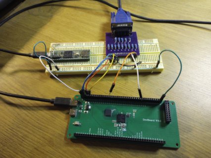
wwatson replied to the thread Call to arms | Teensy + SDRAM = true.First simple experiment on SDRAM board works. Adapted my 4-bit VGA library based on @jmarsh's driver to the dev board. Just had to change two pin defines for FlexIo2 for HSYNC and VSYNC which is used in several places in the FlexIO begin method...
-
-
The solder paste used on these boards are high temp 260c, it's actually very good solder. But to get something off you need a good iron and some flux. Or add a little more solder paste from a siringe (the latter is the best and easiest option)...
-
wwatson replied to the thread Call to arms | Teensy + SDRAM = true.Thanks, I do have that document. I ran the oneScanCaps.ino sketch and most of the frequencies had no errors. Interestingly enough 166MHz had one error. I am not sure which cap DQS has on the board. I can barely see it even with a magnifying...
-
wwatson replied to the thread Call to arms | Teensy + SDRAM = true.Just received the sdram development board today:D I ran through all of the test programs that I know about without a problem. I need to make sure I have all of the pinout info for this board. It is a version 4 board. I thought I would start out...
-
-
wwatson replied to the thread Buydisplay 10.1" TFT in parallel 8080 mode and Teensy FlexIO.Thanks, I'll take a look at it. So far it has been my lack of knowledge of FlexIO and DMA that has slowed me down but I'm starting to understand it more...
-
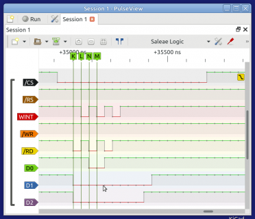
wwatson replied to the thread Buydisplay 10.1" TFT in parallel 8080 mode and Teensy FlexIO.Actually you still need these parts in place of gpioRead() and gpioWrite(): pFlex->setIOPinToFlexMode(12); // For /RD signal pFlex->setIOPinToFlexMode(10); // For /WR signal So here is a a version of lcdDataRead() that works...
-
-
wwatson replied to the thread Buydisplay 10.1" TFT in parallel 8080 mode and Teensy FlexIO.I am using this: pFlex->setClockSettings(3, 1, 0); // (480 MHz source, 1+1, 1+0) >> 480/2/1 >> 240Mhz and here is the FlexIO read setup: FASTRUN void RA8876_t3::FlexIO_Config_SnglBeat_Read() { #if defined(USE_MM) p->CTRL &=...
-
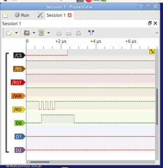
wwatson replied to the thread Buydisplay 10.1" TFT in parallel 8080 mode and Teensy FlexIO.I am trying to find the answer to why doing a FlexIO parallel read results in the /RD signal showing 4 pulses as apposed to the /WR signal showing just one pulse. I have looked all over the net and reference manual with no luck. It's probably...
-
-
wwatson reacted to TFTLCDCyg's post in the thread my SDfat code - good in 2017 but won't compile now? with Like.
In my case, I use IDE 1.8.19 because it is the version that does not give me errors with sketches that have many tabs. The IDE 2.x has given me a lot of headaches. In case of tracking down an error in the code it is easier, the excesses of help...
-
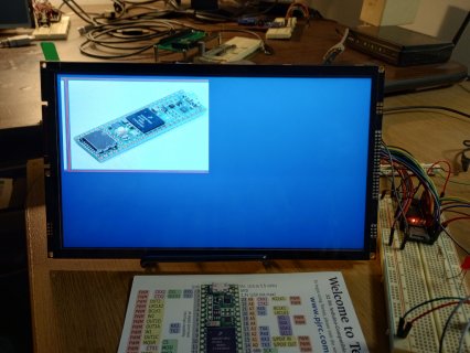
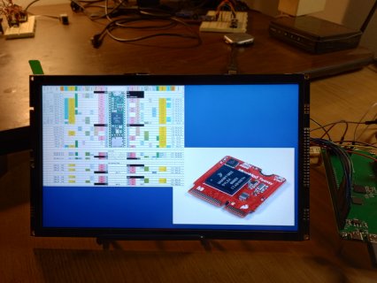
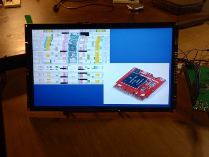
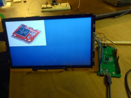
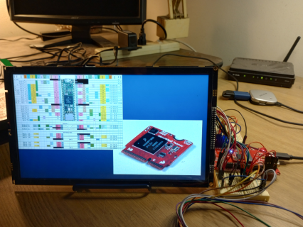
wwatson replied to the thread Buydisplay 10.1" TFT in parallel 8080 mode and Teensy FlexIO.The MicroMod is working with the ER-TFTM101-1 display. Still have to get the DMA portion working on the MicroMod. The images were produced in 8-bit mode none DMA, 100ms to display both pictures. I'm sure DMA will speed things up. By the time...
-
-
wwatson replied to the thread Buydisplay 10.1" TFT in parallel 8080 mode and Teensy FlexIO.Awesome. Now to cover any leftover SPI calls with 8080 calls and then onto the MicroMod. I am really trying keep it all in one library...
-
wwatson replied to the thread Buydisplay 10.1" TFT in parallel 8080 mode and Teensy FlexIO.Good, just finished updating the 8-bit version and the draw time was 29ms for 449280 bytes which would be close to 60ms for 800k...
-
wwatson replied to the thread Buydisplay 10.1" TFT in parallel 8080 mode and Teensy FlexIO.Here is a little background my Ra8876LiteTeeensy library. I wrote the original library. Then @KurtE and @mjs513 decided to optimize it and later @mborgerson added to the library. The the original thread can be found here...
-
wwatson replied to the thread Buydisplay 10.1" TFT in parallel 8080 mode and Teensy FlexIO.That was the issue: Teensy and RA8876 parallel 8080 mode testing (8/16) Bus speed: 40 MHZ Rotate: After Origins Drawing two pictures at 794800 bytes in 16-bit mode Draw time: 26ms This is the code now: void...
-
wwatson reacted to Rezo's post in the thread Buydisplay 10.1" TFT in parallel 8080 mode and Teensy FlexIO with Like.
That seems a bit long? 1024*600*2bpp / 40Mhz is 32.55FPS, which is roughly 30ms per full screen write. How are you getting over 200ms for two 800kb images?
-
wwatson replied to the thread Buydisplay 10.1" TFT in parallel 8080 mode and Teensy FlexIO.Not really sure. Probably should run the same test program using SPI mode on my other display to compare. Here is the sketch I am running: #include "RA8876_t3.h" #include "teensy41.c" #include "Teensy41_Cardlike.h" uint8_t dc = 13; uint8_t cs =...
-
wwatson replied to the thread Buydisplay 10.1" TFT in parallel 8080 mode and Teensy FlexIO.A quick update: I now have the T41 working with the RA8876 display in both 8-bit and 16-bit modes using the Ra8876LiteTeensy library. @Rezo was correct. The 16-bit mode is twice as fast as the 8-bit mode which makes sense when using twice as many...
-
wwatson replied to the thread Buydisplay 10.1" TFT in parallel 8080 mode and Teensy FlexIO.@Rezo - I wired up the T41 for 16bit I/O and did some basic reads and writes. All failed. I hooked up my LA to monitor the first two bits of the high byte and low byte. Was reading 0xff from the status reg which was wrong. It should read 0x50...
-
-
Loading…
-
Loading…