Interesting Temperature Data.

Status
Not open for further replies.

Constantin

Well-known member
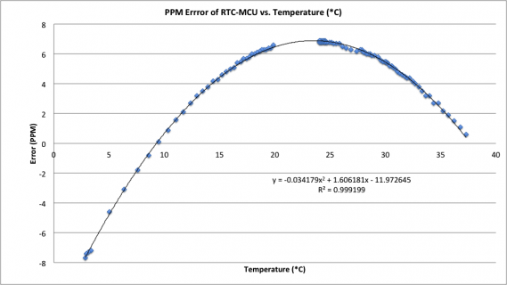
As some of you might recall, I have been experimenting with temperature swings lately with the help of a HTU21 humidity / temperature sensor, the cold winter weather, and a Teensy 3. I had a pretty good experience with the crystal, where I could get the RTC to run at apparently better than 0.5PPM accuracy, simply by periodically polling the HTU21 to see what the temperature was and then applying an open-loop correction factor to the Teensy RTC trim to minimize the temperature-induced error (see second chart to right below).

However, other components like transformers similarly change their output as a function of temperature. Tonight, I did a preliminary test to see what the likely magnitude of the temperature influence is with the voltage transformers I am using for power measurements. Originally, I wanted to do this using two Teensy's (oe at room temp as a control, the other cooled).

Apparently one cannot have two serial monitor windows open at once on a single CPU (at least on a Mac, on Win 7 Pro, the serial window wouldn't open at all, even though I could upload sketches), so the software on both units will have to be revised to write time-stamped data to SD disk. Or, I'll abuse a Yokogawa at work for a day. (which would also do wonders for offset and gain calculations).

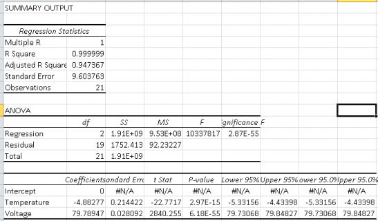
Anyhow, have a look and a laugh. I need to sample a lot more data using better means, but compensating for temperature influences on voltage-transformer- or current transformer-based measurements seems to be pretty justifiable. The regression analysis here [left image]was run backwards to establish the impact on the ADC output. More and better testing is required but the R2, t-stat, p, and F values pretty much speak for themselves.
 

Attachments

  • Clipboard04 copy.png
    Clipboard04 copy.png
    17.3 KB · Views: 357
  • ppm_error.png
    ppm_error.png
    37.1 KB · Views: 476
Last edited:
ever hear of this common issue?
Crystal oscillator in some electronics device like a microprocessor...
power it off.
Cold soak it at like 0F or less for many hours, say 8.
Some circuit designs are such that a cold-soaked oscillator won't start oscillating.

cures include warming blankets and never turn it off.
 
...Cold soak it at like 0F or less for many hours, say 8. Some circuit designs are such that a cold-soaked oscillator won't start oscillating. Cures include warming blankets and never turn it off.

The good news is that my logger is intended for interior use. If it gets that cold inside a house while someone is living there, then they have more important issues to tend to.. like freezing pipes! But your point is a good one. So far, the crystals on the this board (both the MCU crystal and the RTC one) have started up OK each time. But they were only exposed to freezing conditions for a short time, not hours.

This is a good detail to include in the manual, i.e. "if the package was delivered on a day when it was 0*C or less outside, please let it warm for 12 hours before opening". That also helps with unwanted condensation.

What struck me about the collected data is how strongly temperatures influence the output of the voltage transformer. ~5 ADC counts, or 1/16th of a volt, for every degree centigrade deviation is significant enough to warrant some sort of open-loop correction. Is the influence going to be monumental? Not really, considering that the indoor temperatures are likely to remain between 10-30*C (i.e. about +/-0.5V max. deviation). But if the aim is to produce a good power meter, then (however slight) these influences should be accounted for. If anything else, it helps with calibration.

One of the key issues will be characterizing the temperature compensation function for the voltage transformer and the CT (i.e. is it linear, log, x2, etc) as well as determining how consistent it is from transformer to transformer. Ideally, the CT and the voltage transformers will be built super consistently (so they only have to be measured once for the whole group) while also featuring linear correction functions. But life is usually not that easy.

FWIW, once the meter is running, it won't turn off until the line power plug is pulled. So that helps a little. The beastie will be inside a box and the integrated line power supply may also help warm the thing a bit.
 
Last edited:
Apparently one cannot have two serial monitor windows open at once on a single CPU
Why do you need two? If you are trying to monitor the T3's serial port(s), you could have a serial monitor instance (for the USB port) plus one or more instances of putty (or similar program).

Pete
 
Why do you need two? If you are trying to monitor the T3's serial port(s), you could have a serial monitor instance (for the USB port) plus one or more instances of putty (or similar program).

Looks like I'll need to use PuTTY and thank you for the reminder. The reason I want two windows running at the same time is that I want to look at the effect of temperature while using one of them as a control (at room temperature).

I.e. start both at room temperature and take a few minutes of measurements of the same voltage data to help calibrate the two relative to each other at room temperature. Then throw one of them in a cold bin, let it soak in the cold for a few hours, then repeat the experiment. We have a local supplier of dry ice, may stop by to buy some. I also have a variac here, so I may also make use of that. Logging the data to CSV files may make more sense at this point, but grabbing the data from the terminal seemed like a pretty good option also.

One thing to be careful of is the sensor on the HTU21 having low mass, combined with a on-board heater. The two factors mean that the HTU21 will potentially show a much different temperature than the voltage transformer / CT core. To (hopefully) address these issues, I plan on only querying the sensor only once a minute while also enclosing the PCB inside enclosure within a EPS cooler with some cold packs. My Fliuke DMM also allows temperature measurements, may use that as an external reference.

Thanks again for the suggestion!
 
Earlier today, I bought some dry ice to log the impact of temperature on the current and voltage transformers. Since I still had about 20lb of the stuff when I was done with those measurements, I decided to further characterize the error of the RTC crystal as a function of ambient temperature. The data set above has been supplemented with this data.

PPM Error.png

Is the data set complete? No, there is a gap between -10*C and -3*C:eek:. Additionally, I have not yet thought of a good way to heat the enclosure gradually enough to allow measurements of temperatures above 40*C. That said, do I expect there to be a monumental disconnect? Not really, given an R2 of 99.97%. Given how nicely the curve fits, I am somewhat inclined close the issue out. :p

IMO, given the right clock crystal (like this instance of a CFS206), the RTC can achieve very high accuracy through open-loop control simply by periodically polling an accurate on-board temperature sensor like the HTU21. Is the above curve representative of every CFS206 I will ever encounter? Of course not - per Citizen, the OEM, the inflection point can vary from 20-30*C, a fairly wide range. However, the calibration sketch the Teensy now runs allows the board to calculate all the relevant variables automatically, that are then saved to EEPROM for later retrieval.

All that's needed for calibration is a accurate PPS signal and a gradually varying enclosure temperature. Whether this level of effort is worth the time vs. simply spending $9 extra on a DS3231 or DS3232 is left to the reader to decide. I happen to think it makes sense, especially in the context of also verifying / customizing similar open-loop controls for the voltage and current measurements. The closer review of those measurements come next, their data processing is a bit more involved.
 
Last edited:
Ha ha ha, the first casualty

Did some more testing - this stuff is slow to sublime - and can report my first casualty.

Cable.jpg

I think we can safely conclude that this USB cable was not made for the conditions it encountered in the dry ice. Oh well, good thing I recently bought three more!

FWIW, I have more data for the -38 to +22*C range for the crystal. Another 90 data points simply confirming the previous couple hundred. Now the board is slowly re-warming.
 
Here is a different CFS206 RTC crystal (methinks not a 5PPM model) and temperature is measured with a DS18B20 probe nearby. Looks like a pretty good R^2 of 99.98% and the trendline calculated by excel is in violent agreement with the trendline calculated by the Teensy.

Granted, just a few measurements and all that, but promising. Have a few more CFS206's to try out and characterize. The parabolas all feature very good agreement re: a calculated trendline but the trendline is never the same. The good news is that characterizing the CFS only takes about 20 minutes and batch processing should be quite possible. The key issue is putting together a test chamber that allows lots of units to be set up in parallel and then buffering the PPS signal from the GPS receiver across multiple teensies undergoing the same temp test.

2014-09 RTC Error Test.gif

With this sort of accuracy, the next thing this begs to do is to run a open-loop-compensated RTC and see how well it handles variations in temperature. Not quite sure yet how to measure cumulative drift.
 
Last edited:
Status
Not open for further replies.
Back
Top