Hi!
I am trying to build a version of this Teensy 3.2 Sketch and midi-controller circuit that I found online;
https://llllllll.co/t/17-diy-teensy-midi-controller/28539
It's basically just a USB Midi Controller with 17 rotary potentiometers.
I am new to Micro-Controllers and am just trying to figure all of this out.
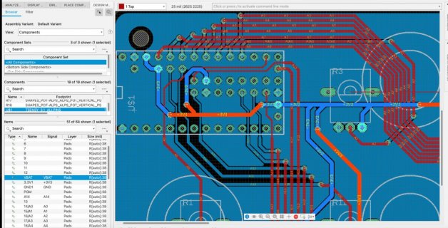
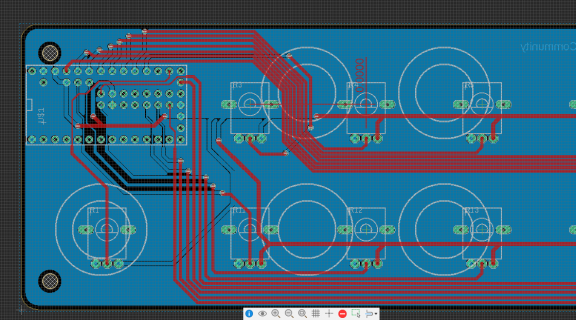
I imported the circuitboard into a demo of EagleCAD so I could see the schematic, as it is not shown on the GitHub for the project.
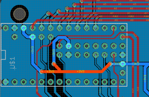
I sort of get how each potentiometer is connected for one of it's pin's, and I see a ground pin shared by all the pots, but don't see how the third pin is connected on each potentiometer?
Also there seems to be inter-connections between pins on the Teensy board itself ("ARef" or something else?) and I don't understand if this is already a default for the Teensy board or what this is doing or if it's necessary?
Thanks!


