confused again. Cutting VIN from VUSB - Teensy 3.0

Status
Not open for further replies.

Russ

Active member
Hello again.

I am planning on running the Teensy from an external power supply but I also want to, when needed, be able to run from the usb in.

When I first bought the teensy and told Paul what I wanted to do he said:

Paul's email said:
If you connect a battery to VIN and you also use USB, cut the pads apart
on the bottom side, to separate VUSB from VIN. You wouldn't want the
USB trying to charge the battery in an uncontrolled way, or the battery
attempting to power your computer when it's off!

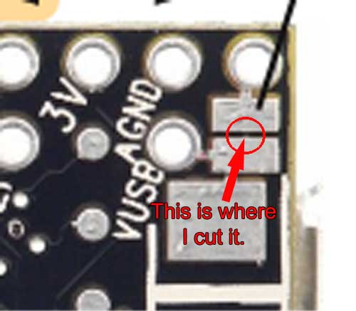
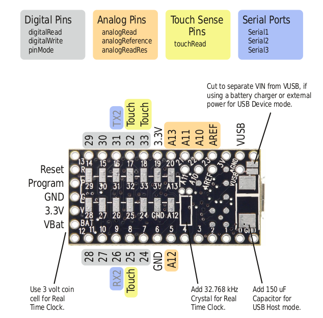
So, today I put the teensy into the breadboard and ran some LEDs from it for the first time. I first ran it from the usb. Once I had my test sketch in place I wanted to test it from the battery so I went ahead and cut apart the pads between VIN and VUSB (or at least I think I did). I am putting up an image to show the trace I cut between the 2 pads.
teensycut.jpg


pinout5b.png


After I did that, I tested it on the meter to make sure the pads were cut then I put it back in the breadboard, hooked up external power and everything seemed to work ok. The strip ran from the test sketch I had uploaded.

But then I plugged the usb back in and disconnected the external power and had nothing. I had no power at the processor and therefore, of course, could not upload any changes to the sketch or anything like that.

So, I then resoldered the pads together and plugged the usb in and could once again talk to the processor and power the test strip. I then connected up external power and after it was connected, unplugged the usb and everything kept running fine. I then replugged in the usb and again everything kept running and then unplugged external and everything kept running. This seems to be what I wanted and from what Paul had said what I assumed I would get with the pads disconnected.

So, what did I do wrong?

Thanks in advance for any insight or advice. It is all very much appreciated.
 
Last edited:
Mainly posting this because I want to know as well.

I have also cut the trace between the pads at the exact spot you marked with the red circle and this is what I notice now:
-When I connect the USB cable to the T3, it is NOT detected by Windows, until I also connect external power.
-When I connect the external power without USB, my sketch runs like expected.

The external power page talks about using 2 diodes to automatically switch to the highest voltage, but I doubt this helpful in the case of a Teensy 3.0


Hey, ok, then it is not just me ;p

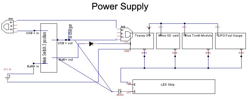
I think I can just throw a diode between the battery and the VIN and I should be ok (at least if the rest of my plan works). I am planning on using a 3 position switch as my main switch.

In position 1 it will have power coming in from the battery pack and going out to VIN and the LED strip. In position 2 there will be nothing so it will be off. Position 3 will have power from the usb in (I broke the power lead out) and going out to the usb and splitting to the charger board and the LED strip. I already have a diode in place on the lead going to the LED strip to stop power from coming back up and getting to the USB so another one between the battery and vin should stop power coming from the usb to the battery (I think). My switch schema should provide the separation of power.

My main concern was if I am cutting it in the right place and what I am missing as to what I expected would happen.

mainswitch.jpg


mainpower.jpg
 
Last edited:
The external power page talks about using 2 diodes to automatically switch to the highest voltage, but I doubt this helpful in the case of a Teensy 3.0

Actually, that should work fine on Teensy 3.0 also. Just solder a diode between those 2 pads, and be sure to use a diode feeding the VIN pin. Whichever power source has the higher voltage will power the board.

Keep in mind that VIN needs 3.7 volts. You diode between the external power and VIN will drop about 0.7 if it's a normal diode, or 0.4 if it's a schottky. That adds to the voltage requirement for your external power.

Hmm, that might screw me up then, having a diode in there anywhere. I am using 3.7v LiIon in parallel as my external supply. So I am right at 3.7 for the most part (with a range of 2.7 (lowest) - 4.2 (fully charged)).. Can't rewire the battery pack without a great deal of effort because it is already in the tube, plus my charger and protection circuits are all for 3.7 v. dilemmas, dilemmas.

I originally had this figured out around the Arduino micro and hoped to be able to just move to the teensy.

Edited in: I think I am ok. I keep forgetting that my switch effectively separates the 2 power supplies except where I am bringing them together at the LED strip. (I don't really need the usb to be able to power the strips actually, just thought it would be a nice to have type thing. To be able to test while programming), so when using usb any power feeding back out VIN is going to a dead pin on the switch. So, I really don't need any diodes in there unless I keep the USB and battery together at the strip.

I just keep confusing myself. So much new stuff to learn. Just like my time in the Navy, it's a f&%$king adventure ;p
 
Last edited:
Well, as always, I am not an expert and I just did what made most sense to me :)

I haven't thought this far ahead yet about multiple power supplies, so I'd like to thank you for posting these images/schematics.
A nice insight on what I should expect when I eventually make the switch from a single power supply to multiple supplies.
 
I'd like to thank you for posting these images/schematics.

You are welcome, however please keep in mind that 1. I suck at diagramming and 2. I know nothing about what I am doing. ;p

But I am glad that they might help in some manner.
 
Ok, all this talk has created another question in my mind and since I do not want to start another thread I will ask it here and maybe someone can help me.

I had (early on) considered using a step-up in this to bring the voltage for the strips up to 5v. I found that they ran just fine on the 3.7v supply I built (bright enough to hurt the eyes actually) so I decided I did not need it.

But, since the teensy needs at least 3.7v and my power supply is built around delivering 3.7v but since LiIon can range from 2.7 at low end to 4.2 at high I am thinking that I might want to boost the voltage going to the teensy a bit.

Sparkfun has a breakout for a 5v step up that looks like it would work but it appears that the current should not be over 200mah (am I reading that right?).

https://www.sparkfun.com/products/10968

This breakout board will accept voltage inputs between 1 and 4 Volts and output a constant, low ripple 5V output capable of sourcing up to 200 mA. This board is great for supplying power to 5V sensors on a 3.3V board, or providing 5V from a AA battery.

My power supply should be pushing around 1800mah (The batteries say they are 600mah and there are 6 of them but everyone says to only expect 300mah out of them) so for working lets call the current between 1800mah and 2400mah.

Do I need to knock down my current some if I put the booster in there?

Also, is my power supply going to cook the teensy?

I have not put the full power supply on to the teensy yet. I have tested the teensy with a single 3.7v 600mah battery and it seemed to work just fine but should I be knocking that current down some?

If I need to knock it down then how much resistance should I be putting in place. I tried to work it out myself and also tried to find an online calculator that would give me an answer but only ended up in my usual place, confused. My voltage is 3.7v my current is 1.8amp and I if I use the booster then I think I need to knock that down to .2 amp.

By my calculations I would have 3.7v/.2amps which would be 18.5ohms resistance needed. Do I have that right? I am confused because nowhere in there is the original input current coming into play.

Ok, I said it raised a question in my mind but then I put 4 or 5 questions in there, sorry about that. Please excuse my confusion, I am old ;p
 
Last edited:
You are welcome, however please keep in mind that 1. I suck at diagramming and 2. I know nothing about what I am doing. ;p

But I am glad that they might help in some manner.

Haha, I noticed before how our signatures are quite similar ;)

It's a nice example and when I saw it, I immediately it had a 'vision' of how to make such connections.
(I don't know the right word, but I mean that I could see it in front of me when I'd close my eyes)
 
Haha, I noticed before how our signatures are quite similar ;)

Yeah, I noticed it too. Maybe we should start a newbie club ;p

I haven't been a newbie at anything in a while. I had kind of forgotten how it feels so it is probably a good exercise for me.
 
Well, they say you're never too old to learn :)

Getting back to your follow up question(s).
I could be very wrong here, but from what I understand the breakout board will draw at maximum (up to) 200mA from any source.

If I read this product description correct:
This lithium ion pack is made of 3 balanced 2200mAh cells for a total of 6600mA capacity!

Combining 6x 600mAh makes 3600mAh, which means you have at least 18hrs battery life at 200mA draw.
If the combined batteries supply only half that amount, you'd still have 9hrs battery life, but that wouldn't change how much the breakout board draws from the battery/batteries and passes on to whatever is behind it.

I'm also not sure (when the above is correct) if the Teensy can handle the 200mA on the Vin, I think so, but I don't know...
 
Well, they say you're never too old to learn :)

Getting back to your follow up question(s).
I could be very wrong here, but from what I understand the breakout board will draw at maximum (up to) 200mA from any source.

If I read this product description correct:


Combining 6x 600mAh makes 3600mAh, which means you have at least 18hrs battery life at 200mA draw.
If the combined batteries supply only half that amount, you'd still have 9hrs battery life, but that wouldn't change how much the breakout board draws from the battery/batteries and passes on to whatever is behind it.

I'm also not sure (when the above is correct) if the Teensy can handle the 200mA on the Vin, I think so, but I don't know...


Ooops on the math error, thanks for that. Yes. It is 3600mah if you believe the battery label. The 2400mah comes from what I was seeing on the meter during testing.

Ok, so that is the power draw, so I would be ok just hooking it into the circuit I assume. On the 200ma on the teensy VIN, wouldn't that work the same way? You apply whatever current but it only draws the 70mah (or whatever) it uses? Like I said in my earlier, I had the teensy hooked up to a single 3.7 600mah battery and it seemed to be just fine.

Thanks for the reply and the insight.
 
Last edited:
That is exactly how I understand it myself (with my limited knowledge).

I would appreciate it if someone more experienced could confirm/verify, because I simply don't know for sure...
 
That is exactly how I understand it myself (with my limited knowledge).

I would appreciate it if someone more experienced could confirm/verify, because I simply don't know for sure...

Our club can be called the DFNs for "Dumb F&%$king Newbies" ;p
 
Since i'm late jumping into this, so i'll start with the original post and we'll go from there.

By default on the teensy, Vcc is connected to the USB Vin. This allows the teensy to be powered by the 5v line present on the USB port. When you cut that pad, you separate Vcc from the USB's 5v line. The teensy needs at least 3.7v on Vcc to operate though. Which is why when it was only plugged into USB with the pad cut, it was off, but it worked with the battery connected to Vcc.. The teensy was being powered by the battery even though USB was plugged up.

Before I go into other issues brought up in this thread, does that explain to you why you saw the behavior you did after you cut the pad?


Hey, thanks for the reply. I have that now, I did not at the beginning. Somewhere between Paul's explanation of the diode and my wandering off to the step-up I realized that was the way it works. Thanks for confirming it.

I originally started my project with an Arduino micro and it auto switches between the power source when you plug in and unplug the usb. The same thing can be accomplished with a diode between vcc and vusb on the teensy. Otherwise, if you cut the pads you are running power from the external power supply always. You can still do logic across the usb though.

Do I have that right now?

Thanks :)
 
As VIN goes less than 3.7, the 3.3 volt line may decrease. The USB is not reliable if it goes less than 3.0, and the SPI is specified for only up to 12 MHz, but other than those limit, Teensy 3.0 can actually run ok until the 3.3 volt line drops all the way to 1.7 volts. Of course, the digital pins only output a logic high at whatever voltage is on the 3.3 volt power.
 
As VIN goes less than 3.7, the 3.3 volt line may decrease. The USB is not reliable if it goes less than 3.0, and the SPI is specified for only up to 12 MHz, but other than those limit, Teensy 3.0 can actually run ok until the 3.3 volt line drops all the way to 1.7 volts. Of course, the digital pins only output a logic high at whatever voltage is on the 3.3 volt power.

That makes sense to this addled brain. So, in that case anything running off the 3.3 out from the processor is also getting decreased voltage. Thus if I have the sdmicro running off of the 3.3 out (and the fuel gauge and the blue tooth) they are also changing.

I think I am going to try the booster. I ordered 3 of them from karlsonrobotics. That should give me a constant 5V going to the teensy and should result in a steady 3.3 coming out.

Now, another question if you will. Should the peripherals be run off the 3.3 out from the teensy or should there be a leg off the external through a regulator or somesuch to give them a separate sup[ply? Sorry if that is a clueless question but...

Thanks again.
 
Hey, thanks for the reply. I have that now, I did not at the beginning. Somewhere between Paul's explanation of the diode and my wandering off to the step-up I realized that was the way it works. Thanks for confirming it.

I originally started my project with an Arduino micro and it auto switches between the power source when you plug in and unplug the usb. The same thing can be accomplished with a diode between vcc and vusb on the teensy. Otherwise, if you cut the pads you are running power from the external power supply always. You can still do logic across the usb though.

Do I have that right now?

Thanks :)

Yes. Though you also need a diode on the battery side as well. What this accomplishes is isolating the battery and the USB from each other. It prevents the battery voltage from ever getting to the USB header, and prevents the USB 5V from charging the battery in an unregulated manner (which is dangerous).

The next thing I see there is contention with is source and draw currents. The numbers I saw being thrown around above frankly for the most part don't have much bearing on anything discussed in the fashion they were (no offense intended)

The place you want to start is finding out exactly what the maximum current draw your circuit has worst case.. That's with the teensy on, and all LED's on full, etc. One way to go about this is to comb through all the respective datasheets and just add it all up. An easier way, at least it would be for me, is to just hook it all up, write a sketch to turn on all the LED's, and run the whole thing off a bench PSU set at 5v and just see how much current it pulls.

Then with that number in hand, you can start determining what boost converters etc are suitable for your need to turn a li-ion or li-po input into regulated 5v with sufficient current capabilities to meet your worse case current draw. The sparkfun part you linked above IMHO isn't likely to be suitable. 200mA maximum is unlikely to be able to power the teensy. From what i've read, when powered properly, LPD8806 strips draw about 60mA per LED when powered properly. (power taps every meter, with both ends of every meter powered) However power consumtion (and brightness) is lower when you only power one end of a long strip.
 
Last edited:
Good morning. Thanks for the reply and do not even concern yourself with offending me. I have been trying to digest tons of information across the last couple of months and sometimes I get very lost.

Ok, a lot to digest there. I looked around for specifics on how much current the teensy and my peripherals would draw (leaving out the LED strips for the moment, I iwll return to them later). It appears that the maximum current draw of the chip on the teensy is 200mah but in discussions I am seeing numbers of around 70mah as actual draw so I will call it 70mah for this discussion. The sd micro card appears to draw a max of 80mah, my fuels gauge has a max of 75uah so that is pretty much negligible. I could not find what the blue tooth adapter I am using is rated at. But I am in the neighborhood of 150mah without it, I think. So, yeah, the 200mah coming off the booster might not be enough. I also found some charts on similar booster boards and they are indicating that the output from the board could go as high as 300mah. This is the kind of stuff that confuses me...lol

Since I already have a couple of the booster boards in the pipe I will wait and see what the realities are on that are before making a final determination.

On to the LED strips. I (believe) that I have the power to the strips and the processor effectively separated by using a switch, so the booster would only apply to the microprocessor and the peripherals not the LED strips.

During my initial research I had seen the information about powering them every meter and had planned to have them set up that way. However I ran across a diy hoop project very similar to what I am doing (http://philihp.com/blog/2011/diy-led-hula-hoop/) and he was running approximately 3 meters of LPD8806 off of 4 3.7v batteries successfully without any power boosting in the equation. During my testing I have run 134 leds off of my 3.7v supply with power only applied at one end without any issues. I have run them with the power directly applied from the battery pack to the strips and also have run them from the 5V output of an Arduino micro. They are bright enough to hurt the eyes and they all light nicely.

Here is a video I posted in my hoop from hell thread showing the LEDs working. That is with the actual 3.7v external supply I am using going directly to the LED strips and an Arduino Micro controlling them. I do not know yet how long they will run but I am past the 1 hour mark at this time. http://www.youtube.com/watch?v=TSsxem_3zOQ

I did attempt to power them every meter at one point but something screwed up and they were not working properly so I dropped back to just powering one end and they seem to run ok. I don't know why, but they do. So, my plan at this point is to run them off the 3.7v supply with power applied at one end. I could pull the strip back out of the tube and try applying power every meter as you (and many references) state but that is a major PIA so I need to know what I would get from it by doing that.

Does that make sense? Please do not take anything I say as an argument because it is not meant that way. I am learning a hell of a lot and trying to digest it all.

On this:

The place you want to start is finding out exactly what the maximum current draw your circuit has worst case.. That's with the teensy on, and all LED's on full, etc. One way to go about this is to comb through all the respective datasheets and just add it all up. An easier way, at least it would be for me, is to just hook it all up, write a sketch to turn on all the LED's, and run the whole thing off a bench PSU set at 5v and just see how much current it pulls.

That would be my way to do it too, see what the actuals are rather than trying to figure it out up front :) However I am not sure how to measure what the current draw would be. I will try to research it some but any advice as to what I should measure and where I should measure it from would be greatly appreciated.

Thanks again for the reply and the information. It is very helpful.
 
Last edited:
Ok. if your only trying to power your microcontroller, etc off the boost converter, 200-300mA is probably plenty. I was under the assumption you were powering LED's and all from it.

About the only thing I can think of to watch out for is low voltage. You need to see how your LED's are going to perform at 2.7V if you're going to be driving them directly from the batteries. The datasheet for the LPD8806 indicates the IC itself will work down to a 2.7V VCC though that's the absolute minimum. Recommended is 3.3V-5.5V. I don't know what kind of brightness your LED's will have at that voltage though.

Hello again :)

Hopefully, if everything works as expected the circuits cut off around 2.7v to stop from battery overdrain.

Thanks.
 
It's not really battery drain I was talking about. It was actual LED brightness and the LPD8806 IC's performance when your voltages get that low. Like I said. You'll just have to test it and see if it's suitable to your needs.. Just remember, as your batteries drain, your LED's will get more and more dim. It just depends on how low you're willing to go.
 
It's not really battery drain I was talking about. It was actual LED brightness and the LPD8806 IC's performance when your voltages get that low. Like I said. You'll just have to test it and see if it's suitable to your needs.. Just remember, as your batteries drain, your LED's will get more and more dim. It just depends on how low you're willing to go.

Thanks, yeah I have not run them down far enough yet to see what they will look like. I am hoping to get 3 or 4 hours between recharges. I think that should be plenty, I hope ;p
 
Status
Not open for further replies.
Back
Top