Creating 150khz sine wave

Status
Not open for further replies.

kushagra

Member
Hello everybody,
I am trying to produce a 150 khz sine wave from the teensy 3.6 I understand that this is far greater than the DAC speed according to the spec sheet. I was wondering if this is possible to do with the timers on the teensy 3.6 and has anybody tried ?
My final application is to produce a Binary FSK transmittion at around 600 bps using just the Teensy 3.6.
 
Sounds like a job for a DDS module, not a microcontroller. Cheap AD9833 module perhaps?

Or you could use square wave output and a high-order low-pass filter on the output to kill the harmonics.
 
Sounds like a job for a DDS module, not a microcontroller. Cheap AD9833 module perhaps?

Or you could use square wave output and a high-order low-pass filter on the output to kill the harmonics.


I understand. Is there anyway to do it natively on the teensy ? maybe with some LPF attached ?
 
In theory, you could connect resistors in a R-2R ladder or just binary weighted to several pins and write 8 bit numbers to a native port. You'd probably set up a timer to trigger a DMA channel to copy bytes from a buffer to the pins. It would probably look similar to the code in OctoWS2811, except using only 1 DMA channel instead of 3, since you just want to write all the pins once per update rather than 3 times.

Realistically, you can probably expect to get about 3 to 5 million updates per second using DMA, for about 20 to 33 updates per period of 150 kHz.

To do this, you'll need to dive into some fairly low-level coding. Probably best to start with OctoWS2811 and connect resistors to the 8 pins. I'd suggest starting simple with the code, like configuring the LED strip length to be the number of points per waveform and fill the output buffer with your sine wave data. When you watch the waveform on your oscilloscope, you should see an 800 kHz waveform for the LED protocol, where the first part is maximum voltage because all pins drive high, then your analog voltage should be in the middle part, and the last part should be minimum voltage because all the pins drive low. Before you dive into the complexity of timers and DMA channels, I highly recommend just using the existing code as-is (maybe even use setPixel with specific colors to get your sine wave written into the buffer) to get to that point.

Once you get that waveform, then the next step would be cutting away the 2 unneeded DMA channels, so you're not driving the pin high and low at the beginning and end of each 800 kHz cycle of the timer. Again, get that working before messing with the timer. The key to success with this sort of project is approaching it in small steps and leveraging each success to move on to the next. If you just start tearing into all the complex hardware details at the same time, odds of getting everything working are slim.

Hey Paul thank you for replying. Sounds like a fairly daunting task. What would be the simplest solution to generate a BFSK signal at 600 BPS from the Teensy 3.6 considering that I am willing add some cheap single module ? Also is it possible to do it easier on some other teensy revision (4.1 ??)
 
BTW what signal quality requirements do you have?


Hey Mark, I don't have specific signal requirements per say. My goal is to make an AM transmission with minimum parts added which uses B-FSK at 600 BPS. I guess I can add filtering externally if the signal is too dirty to transmit. At such low frequencies the transmission will be so inefficient with any traditional antenna setup that I think it wont go far anyway so will be very close range. What do you recommend ?
 
Sorry I did not mean Amplitude modulation. I mean B-FSK modulation at 150 khz frequency :p I am a radio guy yet I mix frequencies and modulation :p
 
When I suggested you connect only resistors and adapt the OctoWS2811 code, you said:

Sounds like a fairly daunting task. What would be the simplest solution to generate a BFSK signal at 600 BPS from the Teensy 3.6 considering that I am willing add some cheap single module ?


Then when Mark asks about your requirements:

My goal is to make an AM transmission with minimum parts added which uses B-FSK at 600 BPS. I guess I can add filtering externally if the signal is too dirty to transmit.


There is no magical answer here, like someone has already done a very similar project and shared their entire design as open source. **

We can try to help you, but you're going to have to do some work. If you build a crude-but-fast DAC using pins and resistors, you can put that work into the software side to synthesize the waveform at high sample rate and stream it to the pins. Or if you want to keep things simpler (maybe even just a matter of using analogWriteFrequency 600 times per second), you can generate a square wave and put work into the difficult filtering to remove the harmonics.

I do have one question... I missed it in these 10 messages, but have we even heard how far you wish to modulate (or "shift") the 150 kHz frequency?


** - Unless Frank comes along and shares his FM modulation with PLL & DMA wizardry...
 
Hey Paul,
A shift of 0.5 khz is what I am aiming for.
So between the space and mark frequency a shift of 500 Hz. I understand what you are saying, I am just trying to wonder if there is a simpler way to produce the same signal. Kind of spoilt from using high speed DACs and ADCs in moderns SDRs I guess :p
 
For transmission quality I don't think direct from a microcontroller is clean enough, all that digital noise on the rails...

Something like a DDS-60 module might be more reasonable, but with modifications to go below 1MHz.
 
Makes sense I guess. I might try an AD9833 DDS module from Analog Devices which is a bit low spec compared to the AD9851 in the DDS-60 but I need 150 khz anyways so it doesn't really matter. Read that it should be able to do basic B-FSK with the two internal frequency registers from the datasheet. Thank you for helping !!
 
A basic idea without any details: you could set up a PWM pin at 150 khz, set up another PWM pin at 150500 hz, run those outputs to a 2:1 mux and toggle the mux select pin at the 600 baud rate. And then lowpass filter the output.
 
Isn't turning a square to a pure enough sine pretty difficult, analog filter wise?

A chip like AD9833 could give a nice sine with harmonics all above 20 MHz, which ought to be pretty easy to filter away.

Doing it with only resistors and DMA to the pins would probably achieve 4-5 Msample/sec and about 5 or 6 bits resolution. So more harmonic content around 5 MHz to filter away.... but only ordinary 1% resistors, and much more on the software size to synthesize the waveform and maintain the high data rate with DMA buffers.
 
Sounds like a job for a DDS module, not a microcontroller. Cheap AD9833 module perhaps?
That was my first thought as well. Since I had such a $2.50 module laying around, I decided to give it a try.
The nice thing about the AD9833 is that it has 2 frequency registers that you can pre-program and than dynamically switch between those 2 registers and thus send out these 2 frequencies alternatingly.

Here is the code:
Code:
// AD9833 bd    Teensy 3.x
// VCC          Vin 5V
// DGND         GND
// SDATA        11 MOSI
// SCLK         13 SCK
// FSYNC        10 SS

#include <SPI.h>
#define FSYNC 10
#define SPI_CLOCK_SPEED 12000000      // 12MHz SPI clock

uint32_t spaceFreqWord = 0x1888f8;    // 150kHz - 250Hz, FreqWord = (frequency * pow(2, 28))/MCLK
uint32_t markFreqWord = 0x189df1;     // 150kHz + 250Hz
uint16_t MSB;
uint16_t LSB;

void setup() {
  pinMode (FSYNC, OUTPUT);
  digitalWrite(FSYNC, HIGH);
  SPI.begin();
  AD9833setFrequencies();
}

void loop() {
  // switch between freq 0 and freq 1
  WriteRegister(0x2000);              // output freq 0 "SPACE"
  delay(50);
  WriteRegister(0x2800);              // output freq 1 "MARK"
  delay(50);
}

void AD9833setFrequencies() {
  WriteRegister(0x2100);              // put AD9833 into reset and tell it to accept 14bit words (DB13=1, DB8=1)

  MSB = (uint16_t)((spaceFreqWord & 0xFFFC000) >> 14);    // only lower 14 bits are used for data
  LSB = (uint16_t)(spaceFreqWord & 0x3FFF);
  LSB |= 0x4000;                      // DB 15=0, DB14=1    FreqReg0
  MSB |= 0x4000;                      // DB 15=0, DB14=1
  WriteRegister(LSB);                 // write lower 16 bits to AD9833 registers
  WriteRegister(MSB);                 // write upper 16 bits to AD9833 registers

  MSB = (uint16_t)((markFreqWord & 0xFFFC000) >> 14);    // only lower 14 bits are used for data
  LSB = (uint16_t)(markFreqWord & 0x3FFF);
  LSB |= 0x8000;                      // DB 15=1, DB14=0    FreqReg1
  MSB |= 0x8000;                      // DB 15=1, DB14=0
  WriteRegister(LSB);                 // write lower 16 bits to AD9833 registers
  WriteRegister(MSB);                 // write upper 16 bits to AD9833 registers

  WriteRegister(0xC000);              // write phase register 0
  WriteRegister(0xE000);              // write phase register 1
  WriteRegister(0x2000);              // take AD9833 out of reset, output freq 0
}

void WriteRegister(uint16_t data) {
  SPI.beginTransaction(SPISettings(SPI_CLOCK_SPEED, MSBFIRST, SPI_MODE2));
  digitalWrite(FSYNC, LOW);           // set FSYNC low before writing to AD9833 registers
  SPI.transfer16(data);
  digitalWrite(FSYNC, HIGH);          // write done, set FSYNC high
  SPI.endTransaction();
}

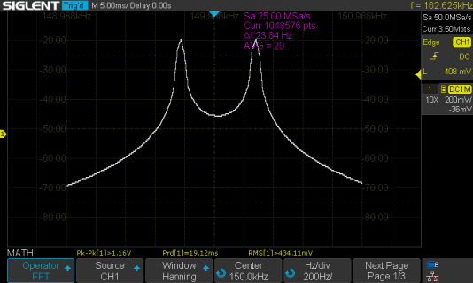
...and the spectrum on pin "OUT":

SDS00039.png

Seems to work.

Paul
 
Status
Not open for further replies.
Back
Top