Custom Teensy DCDC_PSWITCH 2.3 Volts

murdog

Active member
Hi,

I'm on my 5th iteration of a custom teensy board. The first 4 have worked, but, the current one is not, and, best I can tell the issue is DCDC_PSWITCH is at 2.3v instead of the 3.3v I see on my other boards.

Pin 1 of the bootloader is receiving 3.3v, and pin 3 of the bootloader is at 2.3v as well as R6 is at 2.3v.

1) would this apparently low voltage cause the teensy to not be recognized?
2) any idea what would cause the low voltage? Wrong r6 resistor value? Bad connection of the bootloader to the board? Short to ground?

Thanks.
 
I assume you are talking about a Teensy4.x-based custom board.
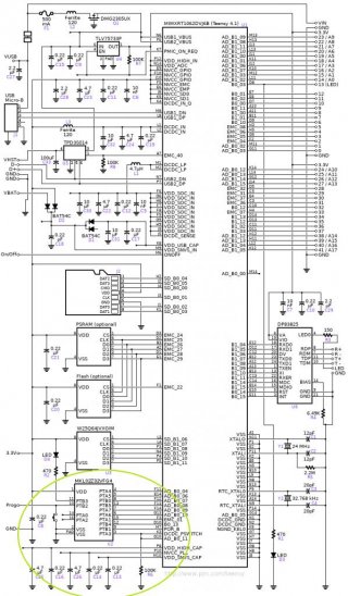
Had a look at the schematic of the Teensy 4.1:

schematic41.jpg

"1) would this apparently low voltage cause the teensy to not be recognized?" > possibly. 2V3 is definitely no good.
"2) any idea what would cause the low voltage? Wrong r6 resistor value?" > possibly, check resistance
" Bad connection of the bootloader to the board?" > possibly
" Short to ground?" > possibly

From this page: PJRC does not recommend using a resistor-capacitor delay circuit to control DCDC_PSWITCH. This signal is not level sensitive. Simply being high will not enable the switching power supply. A low-to-high transition is required after 3.3V power is stable to cause the buck converted to start up.
I assume that your design is pretty much the same around the bootloader chip?

You have a working rev 4 board, so you could compare signals, continuity, resistance, etc.

Paul
 
Thank you for the response.

Yes, it's a Teensy 4x.

Yes, the design is pretty much the same around the bootloader chip, I'm using the design linked on the bootloader page. https://github.com/jenschr/Teensy-4.1-example

I checked the resistance of R6 on both my working rev 4 and not-working rev 5 boards and they are both ~74k. (Not sure why they are not the 100k).

"you could compare signals, continuity". On the Rev 4 board VDD_USB_CAP is 3v and on he rev 5 board VDD_USB_CAP is 2.5v. That and the 2.3v are the only differences I've found.

Thank you again!
 
Also, I'm not sure if you had anything particular in mind with regard to "comparing signals".

Thanks!
 
One thing I did not check was the bootloader pin 2 ground connection. When I did, it was open circuit. Hit it with soldering iron and now everything works!

Thanks again, Paul!
 
Back
Top