Customize the Teensy Loader and using the LPUART to load the code

Hi All,

I recently purchased the Teensy 4.1 and I like it. There are a few things I'd like to ask and possibly need some help with. I want to incorporate the MIMXRT1062 device into my design and I would like to add the Teensy loader chip as well if that is ok to do? I don't want to cause any trouble and figure I ask before even attempting to do it. If it is possible, can you share information about doing this?

Since my design is going to be an industrial board, I need to have the USB interface isolated from the PC side. There are two ways I can see doing this. One is using a CP2102N USB to serial device which I do now on production boards I already make and use a RX and TX line isolator chip which works well OR use a high-speed USB isolator. There are only two available or almost available for high speed 480 mbps data rate but they are expensive and not available for sale until next year.

I really want to go with the USB to serial chip and isolate the RX and TX and then feed that into the MIMXRT1062 device. The UART speed is 115200 baud which is slow. Can I use the LPUART to upload new code to the MIMXRT1062 through the Teensy loader application? If not is there a way to do this through command line or something and then I can write a program in Visual C# to communicate with the bootloader? Also, can I change the loader application to say Vms Bootloader or something like that? Can I pay to have it done? It looks like NXP did something in Python but it is rather complex, and I don't know Python. Also, NXP engineers are hard to get anything beneficial from. All I want is something simple for my customers to upload new firmware to their boards in the field and I want it to have my company name etc. I will not need any security because I already use the ATSHA204 to protect my designs.

Any help with the above would be great.

Thanks,

Eric Norton
 
Quick answers....

I want to incorporate the MIMXRT1062 device into my design and I would like to add the Teensy loader chip as well if that is ok to do? I don't want to cause any trouble and figure I ask before even attempting to do it. If it is possible, can you share information about doing this?

You can get the bootloader chip here.

https://www.pjrc.com/store/ic_mkl02_t4.html

Details on that page about how to use it. The power up sequence is important. Hopefully the info on that page helps you to get your design started in the right direction.


I need to have the USB interface isolated from the PC side.

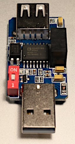
Teensy 4.0 & 4.1 work fine with many inexpensive USB isolators. Here is a cheap no-name one I have on my workbench using the ADUM3160 chip.

usb_isolator.jpg

I plugged it in just now and uploaded a program. Works fine, both uploading and connecting with Arduino Serial Monitor after upload (USB device disconnect and reconnect). Speed is only 12 MBit/sec when this is connected between Teensy and a PC.


I really want to go with the USB to serial chip and isolate the RX and TX and then feed that into the MIMXRT1062 device.

This definitely will not work. Teensy's bootloader does not support serial. Only USB works.


is there a way to do this through command line or something and then I can write a program in Visual C# to communicate with the bootloader?

Yes, command line source code here.

https://github.com/PaulStoffregen/teensy_loader_cli

People have written 3rd party loader programs. TyCommander is the most popular.


Also, can I change the loader application to say Vms Bootloader or something like that? Can I pay to have it done?

Today, no. But it is a feature PJRC is considering offering for Lockable Teensy in the future.


I will not need any security because I already use the ATSHA204 to protect my designs.

Even if you use an external crypto chip, I would highly recommend also using the code security feature of Lockable Teensy. It costs nothing extra, just a minute of your time to use Tools > Teensy 4 Security (must use Arduino 1.8.x, not yet supported in Arduino 2.0.x) to create your encryption key. Then a .EHEX (encrypted) file will automatically be created every time you compile. It's very easy.... (not any extra work as with using NXP's tools).

If you make your own PCBs with the bootloader chip, they will automatically have the lockable feature (unless you run the program shown under "Disabling Boot Configuration Changes" before locking secure mode).
 
Quick answers....


You can get the bootloader chip here.

https://www.pjrc.com/store/ic_mkl02_t4.html

Details on that page about how to use it. The power up sequence is important. Hopefully the info on that page helps you to get your design started in the right direction.


Teensy 4.0 & 4.1 work fine with many inexpensive USB isolators. Here is a cheap no-name one I have on my workbench using the ADUM3160 chip.

View attachment 29733

I plugged it in just now and uploaded a program. Works fine, both uploading and connecting with Arduino Serial Monitor after upload (USB device disconnect and reconnect). Speed is only 12 MBit/sec when this is connected between Teensy and a PC.


This definitely will not work. Teensy's bootloader does not support serial. Only USB works.


Yes, command line source code here.

https://github.com/PaulStoffregen/teensy_loader_cli

People have written 3rd party loader programs. TyCommander is the most popular.


Today, no. But it is a feature PJRC is considering offering for Lockable Teensy in the future.


Even if you use an external crypto chip, I would highly recommend also using the code security feature of Lockable Teensy. It costs nothing extra, just a minute of your time to use Tools > Teensy 4 Security (must use Arduino 1.8.x, not yet supported in Arduino 2.0.x) to create your encryption key. Then a .EHEX (encrypted) file will automatically be created every time you compile. It's very easy.... (not any extra work as with using NXP's tools).

If you make your own PCBs with the bootloader chip, they will automatically have the lockable feature (unless you run the program shown under "Disabling Boot Configuration Changes" before locking secure mode).


Hi Paul,

Thank you for the helpful information I really appreciate it. Ok so if I use the ADUM3160 I am assuming the USB interface is setup for full speed only not high speed? My application needs to go fast, and I also need to use the PSRAM for large buffers. How fast can data be written to and read from the PSRAM chips? Is it 133 MHz? How much "fluff" (extra CPU cycles) is in the Arduino code that interacts with the MIMXRT1062? Does the USB to serial conversion eat up CPU time to manage the data transfer? Can I access the serial receive interrupt for single byte receive event? I also need to use the TX empty interrupt and also be able to enable/disable the TX empty interrupt. Can the USB to serial conversion in Teensy do this? The application I will be porting over to Teensy 4.1 is a high-speed g-code interpreter I created and would like to know if the stuff in the background would interfere with its operation like the timer interrupt, serial interrupt etc.? Also how do the delay functions (delay millisecond and delay microsecond) operate? Are they interrupt driven or are they wait cycle type like a while loop? Any help is appreciated :).

Thanks,

Eric Norton
 
Wow, that's a lot of questions! Here's some answers, but I just don't have time to write a detailed explanation of the internal design of so many things. Hopefully this quick stuff still helps?

Teensy 4.1 USB is normally 480 Mbit/sec, but will automatically run at 12 MBit/sec when connected with the ADUM3160 isolator. Like all 480 Mbit USB devices, it also automatically runs at 12 Mbit if plugged into an ancient PC or USB 1.1 hub.

Those ADUM3160 isolator products are under $20 on Amazon, so probably simplest thing is to just get one and experience it for yourself.

PSRAM is used by adding EXTRAM to arrays or variables you want the compiler to allocate in that memory. Scroll to the bottom of the PSRAM page for an example.

https://www.pjrc.com/store/psram.html

We've had many conversations on this forum about PSRAM performance. It's much slower than internal RAM, but cached, so overall performance depends on memory usage patterns and how many cache misses. Typically people put large arrays or buffers in the PSRAM and use the much faster internal RAM for all other variables.

Most people use the existing serial code which handles interrupts and implements transmit and receive buffers. If you really want to dive into that code, you certainly can, but it's quote complex especially for the USB stuff. It's already pretty efficient, so probably not much to be gained.

Serial data usually doesn't arrive 1 byte at a time. The hardware serial ports have small FIFO. The USB controller in Teensy 4.1 handles (potentially) large transfers as a single operation. The existing code is designed to leverage these features. The hardware serial ports can easily handle megabits/sec baud rates. The USB port is capable of quite impressive speed when running at 480 Mbit. Again, it's been discussed many times on this forum....

Normally the systick timer interrupt has negligible impact. A lot of work went into the many timing functions. You can see all their source code if you really want to know how they work internally.

Obviously delay(), delayMicroseconds() and delayNanoseconds() will busy loop. They don't block interrupts, but they don't return until the amount of time has passed. That's their purpose, if you want to wait. Normally they're not used by programs designed for higher performance.

To implement timing that doesn't block, usually elapsedMillis and elapsedMicros are best for implementing timeouts and other things without adding any extra interrupt overhead.

https://www.pjrc.com/teensy/td_timing_elaspedMillis.html

If you need extremely precise timing and you're willing to deal with interrupts, IntervalTimer is usually the way.

https://www.pjrc.com/teensy/td_timing_IntervalTimer.html

From the nature of your questions, I'm guessing you do not yet have a Teensy 4.1?

It's very fast. If you want to test how the speed compares with other Arduino compatible boards, here are a couple benchmark programs which you just upload with Arduino and watch for the results in the serial monitor window.

https://github.com/PaulStoffregen/CoreMark

https://github.com/PaulStoffregen/USB-Serial-Print-Speed-Test/blob/master/usb_serial_print_speed.ino
 
Hi Paul,

Thank you for clarifying all of that and I do apologize for so many questions. I am used to register level bit twiddling and bare metal programming. I currently use Keil MDK for Nuvoton M481LGCAE devices for my current laser controllers but found that even at 192 MHz it is still not fast enough to handle large file transfers at higher speeds and keep the speed of the stepper motors running smoothly. This is the main reason for wanting to use the MIMXRT10xx series devices as they go much faster. Here are bits of my serial code I currently use for the MIMXRT1011 device with MCUXpresso:

RX and TX interrupt code bits:

// UART Interrupt handler
void LPUART1_SERIAL_RX_TX_IRQHANDLER(void)
{
uint_fast8_t data = 0xFF;
uint_fast16_t next_head;

uint_fast32_t ctrl = LPUART1_PERIPHERAL->CTRL;

if (LPUART1_PERIPHERAL->STAT & (LPUART_STAT_RDRF_MASK | LPUART_STAT_IDLE_MASK)) // Check RX interrupt flag
{
data = LPUART_ReadByte(LPUART1_PERIPHERAL);

.....
}

if (LPUART1_PERIPHERAL->STAT & LPUART_STAT_IDLE_MASK) {
LPUART1_PERIPHERAL->STAT |= LPUART_STAT_IDLE_MASK; // writing a 1 to idle should clear it.
}

if((ctrl & LPUART_CTRL_TIE_MASK) && (LPUART1_PERIPHERAL->STAT & LPUART_STAT_TDRE_MASK)) // Check TX interrupt flag
{
.....
}

if ((ctrl & LPUART_CTRL_TCIE_MASK) && (LPUART1_PERIPHERAL->STAT & LPUART_STAT_TC_MASK))
LPUART1_PERIPHERAL->CTRL &= ~LPUART_CTRL_TCIE_MASK;

__DSB();
}


Enable TX empty interrupt:

// Enable Data Register Empty Interrupt to make sure tx-streaming is running
uint32_t irqMask = DisableGlobalIRQ();
LPUART1_PERIPHERAL->CTRL |= (uint32_t)LPUART_CTRL_TIE_MASK;
EnableGlobalIRQ(irqMask);


Disable TX empty interrupt:

// Disable Tx Data Empty Interrupt
uint32_t irqMask = DisableGlobalIRQ();
LPUART1_PERIPHERAL->CTRL &= ~LPUART_CTRL_TIE_MASK;
EnableGlobalIRQ(irqMask);


The above code is intentionally left like this excluding the in between stuff but gives an idea of what I am doing. From my current testing of the gcode interpreter it runs very fast and works very well. The only downside of the MIMXRT1011 device is the low internal SRAM as the highest I can use and have it configured for is 64K for DTC, 32K for ITC and 32K for OCRAM. 64K DTC doesn't leave me with much for larger data buffers for the RX and TX communication and the segment buffers. I need at least 8K buffer for RX and 8K for TX (holy grail would be 16K for both) and also hoping to use at least 4MB for the segment buffer and 4MB for the look ahead and planner buffer.

I have had success in the past with USB endpoint interrupts for receiving/transmitting data but concerned about the USB overhead from a code point of view and how many cpu cycles it takes while transferring data and managing usb stuff. I want my application to be able to receive and transmit the data as fast as possible and be able to parse and store and output the steps necessary for smoother motor control while under heavy data load.

I'm not a huge fan of Arduino and I have already hooked up the Teensy and played with it a little bit. I am just concerned about how Arduino will slow things down and if so by how much. Would it be negligible? If you say it will be negligible then I will give it a shot.

Thanks,

Eric Norton
 
I believe you should give it a try, and then you can tell me whether the overhead is negligible! :)

The chip on Teensy 4.1 has 1 Mbyte internal RAM, so space for variables isn't nearly so cramped. The partition between ITCM / DTCM is done automatically based on your compiled code size, so you always get as much DTCM as possible while allowing your speed critical code to fit into ITCM.

If you're generating stepper controller pulses from the same loop as the code doing all the input parsing and motion calculations, perhaps consider moving the timing critical pulse generation to IntervalTimer with some sort of command queue for the main program to write the designed pulse timing into.
 
Ok, you win :) I'll give it a go and see how it does.

Ooh interesting, I didn't know it automatically partitions the ITCM and DTCM which would be extremely helpful. The way I currently have the stepper pulse generation is through a set of timers. I will try the interval timer and see how it does. If I have any questions, I will be sure to reach out. Thank you very much for your quick replies and help. It is much appreciated!!
 
Hi Paul,

I tried to work with Arduino and a few other IDEs for Arduino and I just can't work with it. It is too clunky for me. It may be good for others; it just isn't good for me. I wish there was a way to get access to the JTAG for the MIMXRT1062 chip. I see I could unsolder the bootloader micro but the pads are so small it is almost impossible. I guess back to the drawing board...
 
Hi BriComp,

Yes, I have found it and currently moving along at a snail's pace but getting somewhere now. Thank you for recommending it :).

Thanks,

Eric Norton
 
Back
Top