DIY Midi Foot Controler for AxeFX (Guitar Effects Porcessor)

Status
Not open for further replies.
Is there anything I need to consider when deciding whether to use external vs the internal PULLDOWN resistors.

Well, only the obvious concern that the pins will be floating at an undefined level before your code activates the pulldown resistors, and during any code uploads while your program isn't running.

Usually that's perfectly fine if you're using the resistors to have a well defined level for your program's sake. Since you're making a MIDI controller, I'm guessing your needs fit into this case....

Usually it's a problem if you need signal at well defined level for the sake of something else, especially something really important. For example, if the signal controls a driver chip that turns on a motor, you'd probably want a real pulldown resistor so the motor can't accidentally turn on while your code isn't running!
 
Great - thanks Paul.

Sounds like I'm good to go with the INternal Pulldowns.

Can I ask another quick question pls.?
There was a considerable gap between me getting MIDI OUT working & then implementing MIDI OUT in my project.
I noticed last night I have my MIDI IN circuit connected to the 3.3V pin on the Teensy, as opposed to the Vin (3.7 to 5.5 v).
MIDI OUT meanwhile is connected to Vin (3.7 to 5.5 v).

Both work - but does it matter?
 
If it works, what is the problem ??? midi out is based on 5v anyway ... ...

BUT on the the other hand, using the teensy Vin could give you too much in the way of voltage fluctuation to stay in spec for Midi, so maybe a more stable regulated approach would be to use the 3.3V pin with the correct resistor value ...(I'm sure you have seen the note on this page about 3.3V teensy 3.x and 47OHM resistors)

On the other other hand I don't know what your scematic looks like, and it might be a reasonable decision to use Vin ... its working, right?

As to you code problem in your earlier post, I notice that you call MIDI.getSysExArray() twice ...?

Hi - thanks.

Yes it does work - but I do get the odd glitch now and again.
So thought I would double check before I start soldering everything up.

My schematic for IN is as per that page - ie using the 2 x 47 ohm resitsors AND with Pin 4 connected to 3.3v as opposed to Vin. (which the note specifies).
I can't recall why my IN is connected to Vin.
 
Well you don't want glitches while u are performing ... maybe try 3.3V with the 47ohm resistors on your output in case it is some queer fluctuation on the uSB power line that is mucking up your output signal, spec-wise .... (teensy Vin is powering your output, right?) ... you would think it wouldn't matter, but who knows the configuration of the receiving gear?? Glitches could also be software related .... maybe you have big delays in your program?? IDK
 
My schematic for IN is as per that page - ie using the 2 x 47 ohm resitsors AND with Pin 4 connected to 3.3v as opposed to Vin.

Now I'm confused. OUT is supposed to use 2 resistors.


td_libs_MIDI_sch.gif
 
You require connection to positive supply in three places (ignoring the teensy 3.x).

First a supply for the optocoupler ... this could probably be 5V since it is an optocoupler ... but the one I used was speced for 3.3V, so that is what I did ....

Then you need some juice running through your 270OHM resistor to the teensy serial in / RX ... that should be 3.3V!

And finally, for the line out / TX, you seem to be saying that is already at 3.3V, with the 2 47OHM resistors ... ... good.
 
Excellent.

I've moved from Breadboard to proto-board using 3.3V as advised above - all seems to be working fine.
Thanks.

On a separate theme - I have a button that when pressed - increments through a list - by 1 each time.
Anyone any suggestions to how to make a single (extended) press, perform like a scroll -pls?
So I don't need to repeatedly press the button to increment by several items?
 
Last edited:
FYi - here's an extract from my current code for detecting short & long button presses - which seems to work OK.
I just can't figure out a way to keep executing code whilst the button is still pressed.

Code:
elapsedMillis sincePress;

if ( bouncer2.fallingEdge())                                    
        {
             sincePress = 0;
             bouncer2.update();
        }  
        
else if ( bouncer2.risingEdge()) 
        {
            if (sincePress > 500)
              {
                      .... LONG PRESS CODE ....
               }
            else if (sincePress < 500)
              {
             .... SHORT PRESS CODE ......
              }
         }


..hope my question makes sense.
 
Hmm. Doh!!!!
Just dawned on me.
could it really be as simple as:

[ CODE]
while (digitalRead(buttonPin) == HIGH)
{
....code ....

}

[/code]
 
Hmm. Doh!!!!
Just dawned on me.
could it really be as simple as:

Code:
 while (digitalRead(buttonPin) == HIGH)
 {
   ....code ....

}
 
How about this:

Code:
bool pressed = false;

elapsedMillis sincePress;

if (bouncer2.update())
{

if ( bouncer2.fallingEdge())                                    
          {
             sincePress = 0;
             pressed=true;
        }  
        
else {if ( bouncer2.risingEdge()) 
        
           { pressed=false;
           
              if (sincePress > 500)
              {
                      .... LONG PRESS CODE ....
               }
            else if (sincePress < 500)
              {
             .... SHORT PRESS CODE ......
              }
         }
}
}

if (pressed)
{DO SOME STUFF;}
 
Last edited:
Thanks Adrian - I'll try & give this a whirl tonight.

I've added some comments as to how I've interpreted this - is my understanding correct.?

Code:
if (bouncer2.update())                                                  //DETECTS ANY  CHANGE IN STATE OF THAT INPUT
{
if ( bouncer2.fallingEdge())                                           //IF PIN GOES FROM LOW TO HIGH – ie is pressed – RESET SINCEPRESS
                {
                                sincePress = 0;
                                pressed=true;
                 }  
        
else if ( bouncer2.risingEdge())                                      //ELSE IF PIN GOES FROM HIGH TO LOW ie is released – EXECUTE THIS SECTION 
                { 
pressed=false;
                                if (sincePress > 500)                     //IF THE BUTTON WAS RELEASED AFTER MORE THAN 500 MS THEN ....
                {
                                                .... LONG PRESS CODE ....
               }
                                else if (sincePress < 500)             //IF THE BUTTON WAS RELEASED AFTER LESS THAN 500 MS THEN ....
                {
                                                .... SHORT PRESS CODE ......
                }
                }
}

if (pressed)
{
DO SOME STUFF;
}
 
Yes, I think that is just about right .... I'm pretty sure that fallingEdge() only returns true if there is a change since the last update() (same for risingEdge) so...

call update ... if there is a change [i.e. update() is true], lets look at the change ..... then if the change is HIGH TO LOW!!!! there is a falling edge, and the button is pressed, triggering the timer start, and flagging 'pressed' as true [this flag triggers DO SOME STUFF]...

call update ...if there is no change nothing happens ... the timer still runs... 'pressed' is still true, so you still DO SOME STUFF. The button is still pressed.

call update ...if there is a change, and we look at it and its LOW TO HIGH, we have a rising edge, and the button is released .... this means we check the timer and pressed is 'FALSE' [no more DO SOME STUFF] ....

call update ... if there is no change nothing happens ... the timer still runs... 'pressed' is still FALSE [no more DO SOME STUFF] ... the button is still released
 
How did you get on ...? I added a set of braces to clarify the if else if logic ...I think they are unnecessary , but there you go ... I am thinking in blocks today
 
Last edited:
Hi - sorry - never got a chance to look at this over the weekend.

Will endeavour to take a look early part of this week.

Thanks for asking though.
 
Also - what's the protocol for sharing sketches?

Do I just enclose the full script in CODE tags here - or is there a way to attach files.
 
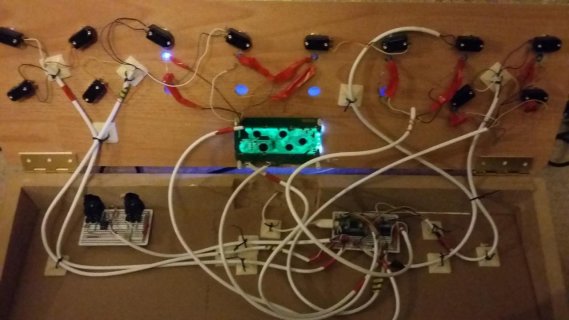
Summary of hardware & Functionality:-

Hardware:
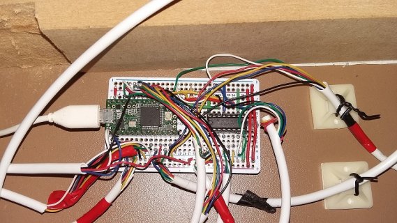
Teensy 3.1
12 x momentary switches
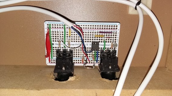
2 x midi sockets
PC900 optocoupler (for midi-IN)
various resistors (mainly for LED's, LCD display & midi IN & OUT)
4 x 20 char LCD screen/display
1 x shift registor
8 x blue LED

I use the Internal Pull-up resistors for all my momentary switches.

Functionality/Switches:
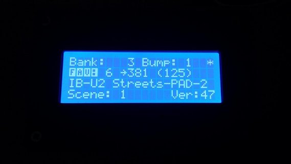
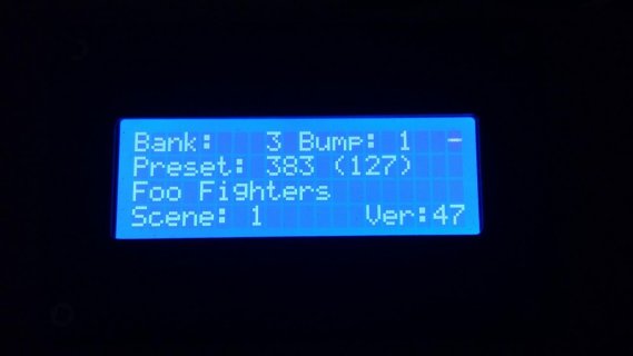
Preset + (increments current preset by the current 'BUMP' value)
Preset - (decrements current preset by the current 'BUMP' value)
Bump (toggles through 3 values) (each press toggles the value to 1, 10 & 30)
Bank + (short press = increments the bank by +1 / long press = reset Bank to 0)
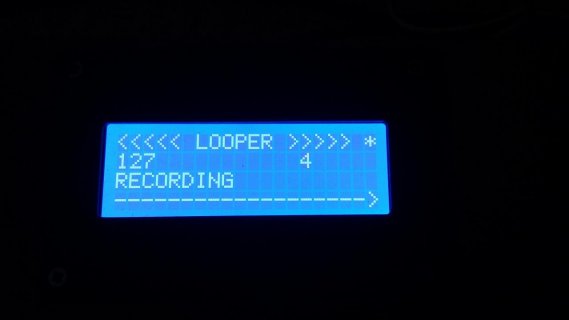
SC1, SC2, SC3, SC4 (selects the respective Scene) (Note: these double up as LOOPER controls when LOOPER mode is enabled - REC, PLAY, DUB, DELETE respect)
SC5 (currently switches the metronome on/off) -plan to remove this and replace with Scene 5 selection.
Looper (enables/disables LOOPER mode - can't recall exactly but this disables some of the other functionality???)
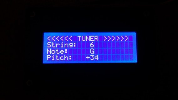
Tuner (enables/disables TUNER mode - - can't recall exactly but this disables some/ALL of the other functionality???)
Fav (enables Favourite mode - which allows selection of 10 'user defined' favourite Presets)(you can configure the number to what every you want).
 
pardon my ignorance ...What is the shift register for ...

And looper and tuner mode ... are they presets on your axefx???
 
pardon my ignorance ...What is the shift register for ...

And looper and tuner mode ... are they presets on your axefx???

The shift register is used to provide extra outputs.

Looper is built in loop station within the axefx.
It allows recording and playback of up to 30 secs audio.
Plus over dubs.

Tuner mode enables the axefx built in guitar tuner.
 
Status
Not open for further replies.
Back
Top