Help with op-amps for high freq signal buffer and voltage adder/mixer

Status
Not open for further replies.

OD_A

New member
Hello,


I am having trouble with a design that I'm building. It is a video synthesiser that controls variable frequencies into the RGB channels of a VGA signal using the Teensy 3.5. I have built similar yet completely analogue video 'hack' synthesisers before, but this is my most ambitious to date using a microcontroller for frequency oscillation.


I use analogWriteFrequency() for three pins with separate clocks to generate frequencies ranging from Hz range to around 1mHz.


What I want to do

I want to buffer the output of each pin, then split to three separate potentiometer sliders (for RGB channels) where I can mix the 'colour' amount into each RGB channel.

I am using a voltage follower circuit for the buffer, and a voltage adder circuit to mix each three outputs into their respective VGA outputs. I chose the LM324 quad op-amp powered with single rail 0gnd +5v from the teensy3.5 USB power, I have also tried using the TL084 and TL072 but I read somewhere that they don't operate well with 3.3v signals on a single rail 0-5v power supply. I have also tried powering IC's from a 9v PSU.

My problem:

I cannot pass voltage through either the voltage follower part of the circuit, or the voltage mixer section. I have used a multimeter and an oscilloscope to conrirm voltage and frequency output from Teensy, and to confirm nothing is passing through the IC's. I have breadboarded and also populated a PCB proto board, checked for any soldering mistakes etc and cannot see anything obvious. I feel as though I am missing something, I lack a thorough understanding of op-amp data sheets to know if an LM324 is suitable for this task and using +5v USB power supply.

Can anyone point me in the right direction, see what I'm doing wrong, or suggest a way I can buffer, split and mix the three frequency outputs from the teensy?

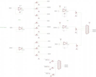
I have attached a quick Eagle schematic I threw together, apologies if it's messy or hard to follow.


Thanks in advance!
 

Attachments

  • Video Synth2_BUFF-MIX.jpg
    Video Synth2_BUFF-MIX.jpg
    58.4 KB · Views: 178
Are you using LM324 or LMV324 (as in the schematic)? They've very similar, but LMV324 can't use power higher than 5.5V. If LMV324s were powered from 9V, replace them with fresh chips!

The first half of your circuit ought to work. You should be seeing *something* at the output of those unity gain followers & the input of those 9 pots. It may not be perfect, but there should be a waveform there. No waveform at all probably means the circuitry isn't connected correctly.

However, the second half doesn't look right at all. Those are configured as inverting amplifiers. If pin 11 was connected to a negative voltage power supply, you ought to get a waveform from 0 to -3.3V when the pot is adjusted for max signal. But with pin 11 connected to GND, you're always going to get zero volts output.

If you really want inverting output, you would need to connect pair of resistors to divide the 3.3V power to 1.65V and connect that 1.65V to the + input on the 3 output opamps.

But there's another problem. Those inverting circuits have a 10K input impedance. You're driving that 10K impedance from a 100K pot. As you turn decrease, the signal amplitude will reduce much more than intended because the high impedance of the pot is loaded by a lower input impedance of the inverting circuit. When you probably meant was a unity gain buffer? If you really want inverting, the simplest solution is probably 3 more opamps as buffers, so the 100K pots aren't loaded and the strong output of the opamp drives that 10K input.

Yet another possible problem is sending extremely fast edges directly into those first 3 opamps. Nearly all opamps are unable to handle such fast edges. How badly it messes up the opamp's feedback is a varies... some opamps do better than others, but none do really well. You'll also certainly need to add RC filter to limit the bandwidth of the signal before it goes into the opamp.

The final issue (at least that I can see just by a quick look) is the LM324 has about 1 MHz gain-bandwidth product. You're not trying for high gain here, but this is video where you probably want at least several MHz bandwidth. But I'd consider this the least critical issue. The LM324s should be good enough for at least experimenting, with the understanding you'll get only limited bandwidth results.
 
Take a look at this spec for VGA - http://www.javiervalcarce.eu/html/vga-signal-format-timming-specs-en.html.

Although the sync signals can be 0 volts to either +3v3 or +5v0, the RGB should only be 0 volts (darkest) to +0.7 volts (max brighness). This means you don't actually want to invert the signals at all (no negative voltages). You can dispense with the 10K's and just use the second stage as a non-inverting buffer (like the first stage).

It also means that if the output from the Teensy is +3v3 then you need to reduce that to +0.7v. This would be best done before the first buffer, and then you would get the "slew rate" of 1 volt per microsecond (as stated in the data sheet) from the amplifiers.

But I suspect there is another design issue with the output from the pins. Does the output from "analogWriteFrequency" go from 0v to 3v3? If so, you are not going to get any analog level variation in the signal. But if that is not a worry, then fine.

Edit: I guess the analog variation comes from PWM. Is the idea to simply change the color of the whole screen rather than pixels? Interesting to see how this turns out.

Also notice you are using pins 6,3,14 which are FTM0, FTM1 and FTM3. Would FTM2 be better than FTM3?
 
Last edited:
Thanks for the replies Paul and TelephoneBill, very helpful.

I can see where I've fallen over a few times here.

Are you using LM324 or LMV324 (as in the schematic)?

- Can confirm, this is my error on schematic. I'm using LM324N IC's specifically.


Ahh... I can see that all I need is a unity gain buffer after the mixing stage, like my input. (I don't know why I decided to use as inverted amplifiers, I think I was blindly copying a schematic I used for mixing audio level signals for an audio synth I built recently).

Yet another possible problem is sending extremely fast edges directly into those first 3 opamps. Nearly all opamps are unable to handle such fast edges. How badly it messes up the opamp's feedback is a varies... some opamps do better than others, but none do really well. You'll also certainly need to add RC filter to limit the bandwidth of the signal before it goes into the opamp.

Am I right in thinking putting a 1k resistor inline then 10nF pull to ground before the first buffer stage will be sufficient for this purpose?


It also means that if the output from the Teensy is +3v3 then you need to reduce that to +0.7v. This would be best done before the first buffer, and then you would get the "slew rate" of 1 volt per microsecond (as stated in the data sheet) from the amplifiers.

- Thanks for the tip, I would usually just step down the output using a trimmer before I send to a projector, so good to know this will help stay within the slew rate of the op-amp.


Edit: I guess the analog variation comes from PWM. Is the idea to simply change the color of the whole screen rather than pixels? Interesting to see how this turns out.

- I'll make sure to post the end result! I'm creating 'scan line' style colour oscillations.

Thanks a lot!
 
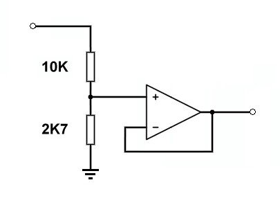
I'd be tempted to breadboard this circuit first for a test run. Use the +5v supply for the chip Vcc.

Cct001.jpg

Its got the right ratio for 3v3 down to 0v7, and I don't think fast edges will upset it because of the 10K providing some degree of isolation.

The problem which might arise is driving into a cable to a monitor. You won't know until you try it.

Op-amps don't like capacitive (cable) loading to their outputs, they might go into spurious oscillations. Some series resistance might then be needed in the output, or possibly a discrete transistor included in the output/feedback to drive the capacitive load.

Trial and error is a good teacher !
 
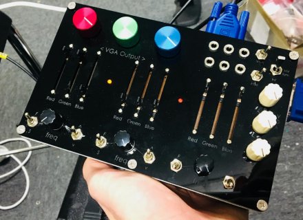
Wow, nice looking build. :)

Let us know if you post about it on your blog. Would be interesting to see what opamp solution you went with. ;)
 
Status
Not open for further replies.
Back
Top