Interfacing with TI DAC856x, DAC816x, or DAC756x

Status
Not open for further replies.

jcarruthers

Well-known member
Hi all,


Does anyone know of a library to interface with the above chips?

Texas Instruments DAC856x, DAC816x, and DAC756x all use the same control code —*so should work roughly the same.

I can't get it going — but it may also be that during my fist attempt to solder an SMD I killed it.

This is what I am trying to send to the chip to no luck:

Code:
//set internal reference
  int c1 = B00111111;
  int c2 = B11111111;
  int c3 = B11111111;
  SPI.transfer(c1);
  SPI.transfer(c2);
  SPI.transfer(c3);
//set both channels to full output
  int c1 = B00011111;
  int c2 = B11111111;
  int c3 = B11111111;
  SPI.transfer(c1);
  SPI.transfer(c2);
  SPI.transfer(c3);


Screen Shot 2014-11-01 at 20.52.57.jpg


James
 
Last edited:
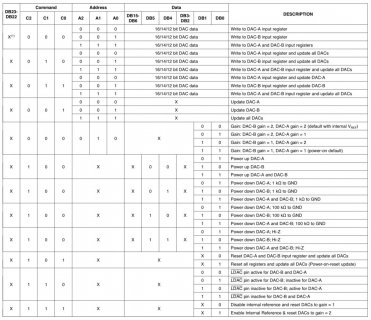
That snppet is not enough to see what you are doing or how you have it wired up. In particular, where in your code do you change SYNC and what are you doing with LDAC and CLR. You also seem to be sending 24 bits while the DAC8568/8168/7568 chips expect 32. Look at table 2 in the datasheet for how to enable the internal reference.

Where does that table come from? It's not in the data sheet I have. And it is missing the prefix bits and feature bits. So:

First decide if you are tying LDAC low or are going to use it. Then (assuming LDAC always low, for now)
- set SYNC low
- send 32 bits as described in data sheet, lsb first
- set SYNC high
 
Last edited:
i don't have libraries, but yep, i can offer working code for DAC8568, DAC8564, DAC8565

edit: it's not clear to me which DAC you're trying to use. roughly the same, yes, but they're not entirely identical. writing to, say, the DAC8565 as such is rather simple; this is still using spi4teensy3 though (the code below assumes RST is pulled high, LDAC, RSTSEL, ENABLE pulled low). for the DAC8564 instead you'd have to get the address bits right etc.


Code:
/*

DAC8565

chip select/CS : 10
reset/RST : 9

DB23 = 0 :: always 0
DB22 = 0 :: always 0
DB21 = 0 && DB20 = 1 :: single-channel update
DB19 = 0 :: always 0
DB18/17  :: DAC # select
DB16 = 0 :: power down mode
DB15-DB0 :: data

*/

void set8565_CHA(uint32_t data) {
  
       		uint8_t _DACout[3];
		digitalWriteFast(CS, LOW); 

		_DACout[0] = B00010000;
                _DACout[1] = uint8_t(data>>8);
                _DACout[2] = uint8_t(data);
       		spi4teensy3::send(_DACout, 3);
                
                digitalWriteFast(CS, HIGH); 
}

void set8565_CHB(uint32_t data) {
  
       		uint8_t _DACout[3];
		digitalWriteFast(CS, LOW); 

		_DACout[0] = B00010010;
                _DACout[1] = uint8_t(data>>8);
                _DACout[2] = uint8_t(data);
       		spi4teensy3::send(_DACout, 3);
                
                digitalWriteFast(CS, HIGH); 
}

void set8565_CHC(uint32_t data) {
  
       		uint8_t _DACout[3];
		digitalWriteFast(CS, LOW); 

		_DACout[0] = B00010100;
                _DACout[1] = uint8_t(data>>8);
                _DACout[2] = uint8_t(data);
       		spi4teensy3::send(_DACout, 3);
                
                digitalWriteFast(CS, HIGH); 
}

void set8565_CHD(uint32_t data) {
  
       		uint8_t _DACout[3];
		digitalWriteFast(CS, LOW); 

		_DACout[0] = B00010110;
                _DACout[1] = uint8_t(data>>8);
                _DACout[2] = uint8_t(data);
       		spi4teensy3::send(_DACout, 3);
                
                digitalWriteFast(CS, HIGH); 
}
 
Last edited:
Thanks guys- sorry for not fully explaining.

I have the the DAC8562 - two channel w/ internal reference.

I have everything wired up for SPI (clk, din (to mosi), sync (ss)) - LDAC is to ground.

There's no addressing a specific chip - only addressing a channel.
 
mxxx I would be interested in your 8568 code.

i haven't used those in while, but i'll dig it up (though it won't look any more elaborate than the above)

as to the DAC8562 -- i haven't used these, so i don't know; the main difference to the quad versions seems to be the internal reference is disabled by default. the write sequence as such doesn't look that much different. you have LDAC pulled low, CLR pulled high? when you set the internal reference, do you see 2.5 v at the output?
 
Turns out I wasn't doing anything with CLR. Thanks all!

Here's my working code:

Code:
// include the SPI library:
#include <SPI.h>


// set pin 10 as the slave select for the digital pot:
const int slaveSelectPin = 10;

void setup() {
  // set the slaveSelectPin as an output:
  pinMode (slaveSelectPin, OUTPUT);
  digitalWrite(slaveSelectPin, LOW);

  // initialise SPI:
  SPI.begin();
  
  //enable internal ref
  digitalWrite(slaveSelectPin, LOW);
  SPI.setBitOrder(MSBFIRST);
  int c1 = B11111111;
  int c2 = B11111111;
  int c3 = B11111111;
  SPI.transfer(c1);
  SPI.transfer(c2);
  SPI.transfer(c3);
  digitalWrite(slaveSelectPin, HIGH);
  
}

void loop() {
  
  unsigned int data = 0;
  digitalWrite(slaveSelectPin, LOW);
  SPI.setBitOrder(MSBFIRST);
  byte c1 = B00011111;
  byte c2 = data >> 8;
  byte c3 = data;
  SPI.transfer(c1);
  SPI.transfer(c2);
  SPI.transfer(c3);
  digitalWrite(slaveSelectPin, HIGH);
  delay(2000);
  
  data = 32768;
  digitalWrite(slaveSelectPin, LOW);
  SPI.setBitOrder(MSBFIRST);
  c1 = B00011111;
  c2 = data >> 8;
  c3 = data;
  SPI.transfer(c1);
  SPI.transfer(c2);
  SPI.transfer(c3);
  digitalWrite(slaveSelectPin, HIGH);
  delay(2000);
 
  data = 65535; 
  digitalWrite(slaveSelectPin, LOW);
  SPI.setBitOrder(MSBFIRST);
  c1 = B00011111;
  c2 = data >> 8;
  c3 = data;
  SPI.transfer(c1);
  SPI.transfer(c2);
  SPI.transfer(c3);
  digitalWrite(slaveSelectPin, HIGH);
  delay(2000);

}
 
Mildly disappointing initial results.

Using the internal reference with gain set to two I expect 0 to 5v = 0 to 5 octaves. If I set up C on my VCO with 0v (it has a frequency display) and then change the DAC to output 5v I don't quite get C+5

That's with the DAC directly plugged in to the VCO - no opamp etc

The Teensy did better with accuracy.
 
Last edited:
Mildly disappointing initial results.

Using the internal reference with gain set to two I expect 0 to 5v = 0 to 5 octaves.

The characteristics that affect your input data to ouput voltage relationship are, for the DAC:
- the number of bits (16)
- the integral non-linearity (±4typ ±12max LSB)
- the differential non-linearity (±0.2typ ±1max LSB)
- the offset error, and zero-code error, which affect the whole line and in particular the values near counts of zero (±1typ ±4max mV offset, 1typ 4max mV zero-code)
- the full-scale error, which affects the values near max count (±0.03typ ±0.2max %FSR)
- the gain error, which affects the slope of the line (±0.01 typ ±0.15max %FSR)
- the initial accuracy of the voltage reference

and then the way all of those change with temperature. The spec sheet uses a variety of different units for these, to hide the scary large values. Convert them all to mV or μV. Yes, 0.2% FSR is 10mV.

For the surrounding circuitry, also consider
- the power supply (needs to be greater than the voltage you are outputting)
- noise on the ground (affects effective number of bits and how close you can get to zero count)
- the gain and offset of any external buffering
- the output impedance (ideally close to zero, 5Ω for this DAC with no external buffering), and the input impedance of the circuit you are driving (typically 50k to 100k for Eurorack modular).

To isolate the effects of those parameters that affect the end of the line, its typical to measure linearity and gain between values close to, but not at, the extreme count values. For example in the datasheet it says "Using line passing through codes 512 and 65,024" for how they measure linearity.

I suggest measuring the actual voltages you get for the codes corresponding to 0.5V, 1V, 1.5V and so on to 4.5V. That lets you check linearity and slope. Your voltmeter should have a higher accuracy than the DAC you are measuring; for a 16bit DAC providing 0 to 5V 1LSB is 76μV so on a 5V range (or 4V if that is the max on your meter) you are looking at better than 0.1mV precision (50,000 counts or 40,000 counts with only 1 count error). Otherwise, the errors you measure are just as likely to be from your meter as from the DAC.

(My meter for example does not meet that requirement; it has 40,000 counts and ±(0.05%+5) accuracy, so exactly 3.0000000 V has an error of 1.5mV and could measure anywhere between 3.0020 and 2.9980V - that is ±26LSB! So you can only adjust to within the limits of your meter. Check the specs on your voltmeter. Check too the specs on the frequency meter on your VCO and the frequency meter on your volmeter, if it has one. Assuming you have a TipTop Z3000 VCO, it has a display tolerance of 0.5Hz at values below 1kHz and makes no claims regarding accuracy.

If I set up C on my VCO with 0v (it has a frequency display) and then change the DAC to output 5v I don't quite get C+5
"don't quite" tells little, and you mentioned your VCO has a frequency display. How many cents off? If you set up C with 1V, and then send 1V and then 4V how close are those values to C and C+3 (in cents)?

That's with the DAC directly plugged in to the VCO - no opamp etc
OK good so I don't need to ask if you copied some circuit with a 1k output resistor, which is common and causes a perfect DAC to have 0.99V/oct.
Having said that, while it is OK to send the output of a DAC (provided that DAC has short circuit protection) direct to VCAs etc, for pitch CVs whewre you care about accurate tracking over 4+ octaves you will need an output buffer. This should use a precision, low Vos op-amp and precision resistors (better than 1%, better than 100ppm/°C), plus have small value, 25-turn trimmers to adjust the gain and the offset over a range somewhat greater than the worst-case values calculated for your DAC. It should also have the output resistor inside the feedback loop. This is then adjusted to give the correct slope (and offeset, although that is less critical since your VCO can be trimmed for a small offset).

You should be able to get tracking within 20 cents over almost the entire 5V range, with worse values for one or perhaps two notes at the ends.

The Teensy did better with accuracy.
That is a hard statement to evaluate without some measurements. In particular, the Teensy 3.1 did not produce 5V out of the DAC, that much is certain. Also, have a look at the on-chip DAC specifications for Teensy 3.1 and compare them to the DAC you are using.
 
Last edited:
it's hard to believe the onboard DAC would outperform a 5/10$ part, however much those 'ultra low glitch' specs might lie to you. at any rate, for this kind of application, the TI series is tried and tested (µscale, Yarns), i'd say. though even these use lookup tables (well, we can't be sure how µscale works. but Yarns does).

so the diagnosis is: there's some (exaggerated?) non-linearity going on and the output is noisy? (as in audible fluctuations?)

i'd probably focus on:

For the surrounding circuitry, also consider
- the power supply (needs to be greater than the voltage you are outputting)
- noise on the ground (affects effective number of bits and how close you can get to zero count)
- the gain and offset of any external buffering
- the output impedance (ideally close to zero, 5Ω for this DAC with no external buffering), and the input impedance of the circuit you are driving (typically 50k to 100k for Eurorack modular).

it's hard to say, as you didn't tell us what you are doing. is this some TSSOP adapter on breadboard contraption? or did you design a pcb? or?
 
Last edited:
Hey guys,

I guess I was being a bit unrealistic with the "Teensy beats it" — I guess I meant "plug and play" — I've done some more testing now.

It turns out the internal gain circuit wasn't so great — I had it set to 2 (the default when using the internal reference voltage is 2.5v) to give me a 5v range. I set it and the frequencies are all within a hertz now. Comparing the difference between the oscillators natural output (nothing connected) and when I connect up the DAC I can't tell the difference between.

I measured the voltage using my multimeter — everything is spot on except for 2.001 and 2.501 — I think I can cope with that.

I am planning on using the OPA2171 as my op amp. Where should I stick the trim pot?

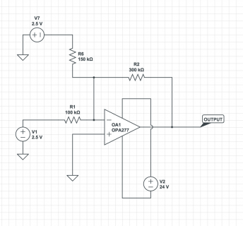
I was planning on borrowing this:

Screen Shot 2014-11-05 at 11.02.54.png

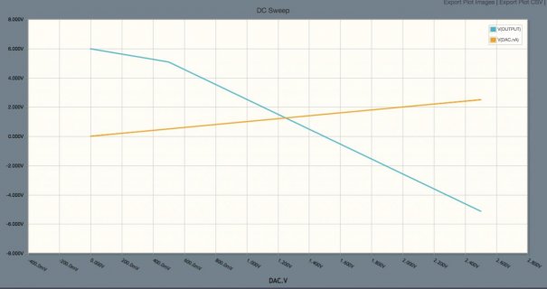
The thing I don't get is that when I put it through Circuit Labs (I wish I had discovered this ages ago — I've learnt so much in a few days from playing) I get a negative voltage.

Screen Shot 2014-11-05 at 11.04.36.jpg
 
Yes, that is an inverting op-amp configuration. The DAC output is going to the negative input. If you want a 0 to 5V range, why put Vref/2 into the positive input? Also, the gain of that circuit is -240/47 = -5.1 ?? So that would get you ±12.7V which you can't even get on Eurorack 12V rails.

You didn't say what the accuracy of your meter was, but if it gives four digit readings then an error of one count (2.501 rather than 2.500) is much more likely to be the meter than to be the DAC.

However, the general circuit (output resistor inside feedback loop, capacitor to control ringing) is about right. A gain trimmer would go in series with R27. Changing the gain to be 0.95 to 1.05 (depending on trimmer position), putting 2* Vref into the positive input, and DAC out into the negative input would get you a 0 to 5V range (but the largest digital code would give 0V and the smallest, 5V so adapt your code to suit).

Your choice of op-amp has Vos = 1.8 mV which is not ideal here (better than TL072A, though). OPA2277PA would be a better choice; Vos = 10μV.
 
Wait, reading about your selected op-amp I see it is rail to rail; and I see your graph has an odd kink at 5V. You are planning to run the buffer from ±12V rails, right? Because on a 5V single rail, the output swing is (V–) + 0.35 (V+) – 0.35 i.e 0.35V to 4.65V, loosing you 0.7 octaves.
 
i was puzzling a bit over those values, too. it seems to swing from -5v to 7.5v (ish) ( - DAC_out * 240/47 + 1.25v * (1+240/47)); i figured that had to do with the Yarns bonus modes.

one could replace the fixed divider (Vref/2) with a trimpot, ie if one wanted to keep things flexible (unipolar/bipolar).

about the gain adjustment -- can't hurt, i guess, but with 16bit to play with, doing it in software probably will do?


Yes, that is an inverting op-amp configuration. The DAC output is going to the negative input. If you want a 0 to 5V range, why put Vref/2 into the positive input? Also, the gain of that circuit is -240/47 = -5.1 ?? So that would get you ±12.7V which you can't even get on Eurorack 12V rails.

You didn't say what the accuracy of your meter was, but if it gives four digit readings then an error of one count (2.501 rather than 2.500) is much more likely to be the meter than to be the DAC.

However, the general circuit (output resistor inside feedback loop, capacitor to control ringing) is about right. A gain trimmer would go in series with R27. Changing the gain to be 0.95 to 1.05 (depending on trimmer position), putting 2* Vref into the positive input, and DAC out into the negative input would get you a 0 to 5V range (but the largest digital code would give 0V and the smallest, 5V so adapt your code to suit).

Your choice of op-amp has Vos = 1.8 mV which is not ideal here (better than TL072A, though). OPA2277PA would be a better choice; Vos = 10μV.
 
It had occurred to me that the ideal output would be -2.5v to 5v —*that way it can do 0-5v for 5 octaves but also be used as an oscillator output (-2.5 to 2.5v)
 
Ahhh right — now I get it... that's what that circuit is doing in the first place. Voltage divider on the VREF.

With 16-bit resolution that makes for a nice solution to be able to do oscillators as well as 1V/OCT.


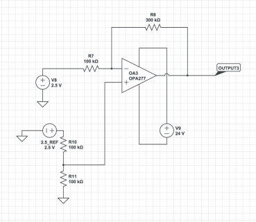
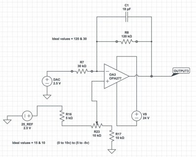
Screen Shot 2014-11-06 at 17.06.18.png
 
So this seems like the ideal circuit — and I presume attests to what was mentioned regards adding a pot to adjust it.

Also I presume that I can take the 2.5v that goes to the op amps + from the DACs VREF output.

Screen Shot 2014-11-06 at 20.56.31.jpg

Adjusts from 0 to 10v all the way to +5 to -5

Useful for both unipolar and bipolar.

What's the guidance on choosing capacitors in such a circuit?
 
Last edited:
A decent ceramic MLCC (C0G/NP0).

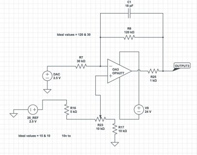
Note that the circuit you have there has no output resistor at all. For outputs that are expected to short to ground during plugging and unplugging patch cords, some 50-100R output resistor (but inside the feedback loop) is advisable. The cap in the feedback loop is before the output resistor and the gain-setting resistor is after it.
 
Last edited:
Aha —*yes — also the 1k "outie" —*that features in the original schematic — I missed it off.

*EDIT* or rather I presume — the "innie" like this:

Screen Shot 2014-11-06 at 23.22.44.jpg
 
Last edited:
Status
Not open for further replies.
Back
Top