JohannGambolputtyEtc
New member
Hi all. I just purchased a Teensy 3, primarily to resurrect a prehistoric PC racing wheel. I'm pretty new to electronics (I know Ohm's law and... well, let's leave it at that for now  ).
).
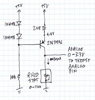
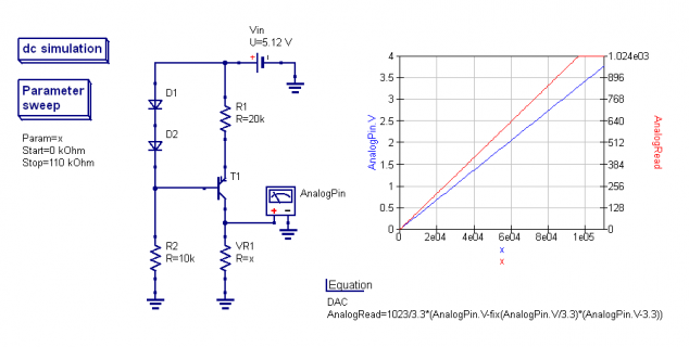
The problem is that the steering axle uses a two-terminal (linear) variable resistor (rheostat?) (110k, 55k when centered) so I can't just connect it without anything else. Adding a fixed resistor makes the signal not respond linear anymore (I can calculate that much). Keeping the current constant would solve the problem, but I have no experience with current sources (or any other components for that matter, apart from following the nice tutorials). Any suggestions on how to get this work? Do you recommend using a constant current source or are there other simple alternatives worth considering? I also found this instructable to make a current source from an op-amp. Any thoughts on that?
Another option is of course to replace the rheostat with a pot, but it would need to have a 180° rotation.
Thanks!


