MINI54 Bringup

Status
Not open for further replies.

jeliason

Member
I'm trying to bring up my first board design using pre-programmed MINI54 chips, and so far I'm not having much luck. I've attached a schematic of the connections between the MINI54ZAN and the MK20256VLH7 annotated with the DC voltages I'm measuring.

I added a 10K pullup from PROG to VDD, and PROG was pulled high, so the 0.14V shown in the annotation is from a floating pin. Based on the Teensy schematic, I would think P5.2 (pin 13) of the MINI54 would have to have a pullup enabled. The fact that it doesn't has me worried. I also added a pullup to RESET_B and confirmed that it is getting actively pulled low.

I'm wondering if something specific needs to be done with the MINI54 /RESET pin (pin 2) during initial bringup. I see now that there is a test point on the Teensy board. Is there a MINI54 bringup sequence I need to follow? I'd welcome another set of eyes.
 

Attachments

  • MINI54_Bringup.pdf
    177.5 KB · Views: 830
  • Controller_Schematic_12-11-14.pdf
    270.6 KB · Views: 847
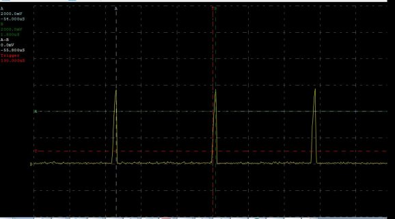
Here's a little more info. The 0.097V on the RESET_B line is due to it periodically attempting to drive high before snapping back low. This happens every 56us. I've observed this same behavior on 3 of 3 boards I looked at, so it's not anomalous. Still suspecting I need to do something with pin 2 of the MINI54 to break out of reset. RESET_B_line.JPG
 
This is normal when the MK20 is completely blank.

The default watchdog timeout is very short. The MK20 repeatedly starts up, but immediately hard faults. Every location is filled with an invalid instruction, causing the first instruction to fault. The default fault handler has an invalid instruction, so the CPU goes into hard fault mode, where it's completely stopped. Then, a short time later, the watchdog time reboots the chip. The reset line is bidirection open-collector, so the MK20 pulls the line low while it's resetting. Then it goes high, and the process repeats as the CPU tries to start up again.

You can check if the MINI54 is alive and working by holding PROG low. While PROG is low, the MINI54 keeps RESET low. As long as you keep holding PROG low (eg, keep pressing the button), you should see reset held low without any activity. If you see that behavior, the MINI54 is alive and working properly. If you see RESET continue to do this while PROG is low, then the MINI54 is not running.
 
Thanks for the quick reply. Holding PROG low didn't change the RESET_B behavior. As I mentioned, PROG is not pulled up by the MINI54 as I would expect, so I also tried adding a 10K pullup to PROG. That also did not change the RESET_B behavior when PROG was pulled low. I was able to probe pin 2 of the MINI54 and see that it is high, so I don't think the MINI54 is stuck in reset.

Regarding the process of getting the MK20 into a valid starting state, I have included the 10-pin ARM header. However, it shares pins with the MINI54, so I foresee some bus contention. Is the expectation that I need to solder pre-programmed MK20's onto the board in the first place?

Thanks again for your support.
 
Holding PROG low didn't change the RESET_B behavior.

Yup, that's a sure sign the Mini54 isn't running properly or isn't connected properly.

Is the expectation that I need to solder pre-programmed MK20's onto the board in the first place?

No, that's not necessary.

We build every single Teensy 3.1 with a blank MK20, where the Mini54 is programmed during a bed-of-nails test, and then the MK20 is programmed with the LED blink via a USB cable, using the normal Teensy Loader running on a Mac.
 
I tried to post this update yesterday, but I guess my login had already timed out.

I just looked in the box of extra parts returned from the assembly site and found the tray of PJRC MINI54ZAN's I had dehydration baked, put in a tray for assembly and dry-packed. They are still sealed. All the other parts were ordered turnkey, and they must have just ordered some blank MINI54's for the build. At least they shipped me back the real parts. Talk about frustrating.
 
I'm going to give them a chance to make up for the mistake first. They worked with me when I made a mistake on my first PCB order, so I'm returning the favor.
 
No problem at all. I should have the reworked boards back by Friday and will hopefully be able to post an update that all is well.
 
I received the reworked boards with the programmed MINI54s and I can program them, and my custom board can do everything the Teensy based prototype can do. The custom boards consistently show up on a different COM port than the Teensy, but everything works.

I fought a few strange issues with my code over the weekend, and my PC's serial communication misbehaved for a while until I unplugged the USB cable and re-plugged it into a different port.

The combination of the Arduino IDE, the Teensy 3.1 / MINI54 and Paul's libraries allowed me to design a highly capable Bluetooth RGB LED controller. We'll be showing the Dancing LEDs controller and light strings at the upcoming Boulder Mini Maker Faire at the end of January.
 
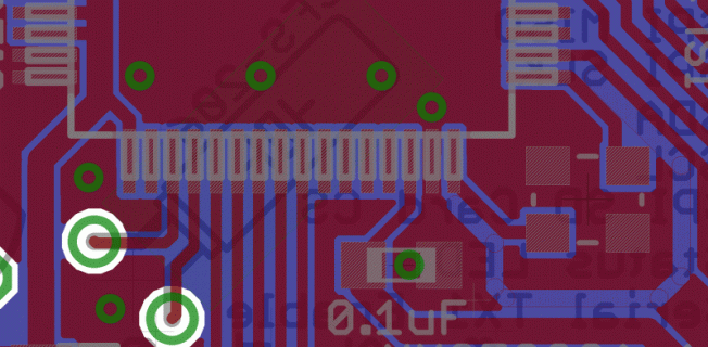
At the very least your capacitor placement for the MCUs is wrong. Power always has to run through the capacitor to the pin. The capacitor has to be close to the pin it is decoupling. Your design shows neither. Instead, you have skinny power lines running willy-nilly under the processor. Plus, the two power pins on the Mini54 also deserve a individual 0.1uF capacitor each.

The ID line does not have to be connected to pin 4 on the USB connector unless you expect to use host mode (which is not supported yet).

Your MiniTan54-MK20DX connections look OK vs. the schematic.

However, it is EXTREMELY unwise to run any power lines, digital lines, etc. under the MCU crystal. Don't do this! Instead, route them around and surround the crystal with a quiet GND area (i.e. separated from the rest of the GND plane and an unbroken GND plane beneath the top layer.

Another big no-no is your use of VIAs for the SPI lines when they don't need to be VIA'd. Simply run the lines out from the corner to bring everything to the SPI connector without using a via. Other connections on the board could easily be done on just the top layer yet use a via to pop down, etc. All you're inviting with this approach is EMI issues. Don't use VIAs unless you have to.

Why did you use a 4-layer board for this effort, as you don't seem to have used the layers as expected? Usually, one or two layers in a 4-board design are used solely as GND and power planes, respectively (or in the case of the Teensy, you may have a split GND plane). There must be a reason you did it differently...

pcb-top.gif
Note how I placed the capacitor such that it decouples the power pin. I had a restrict area around the crystal to keep it happy.

attachment.php

Here is a different design with the MKL02Z bootloader (instead of MiniTan54) showing the use of two large 0-ohm resistors to bring power and a reset signal to the MKL02 bootloader chip. Note, this is a 2-layer design with a nearly unbroken GND plane. I do 'cheat' in these designs by adding one or two jumper wires and resistors selectively to allow me to keep the GND plane whole. Call it OCD, if you will.
 
Last edited:
Yes, the two outer pads on the crystal are supposed to be GND'd per the NX spec sheet.

For me, the biggest concern is why you need to recreate the Teensy. I see nothing on this board that you couldn't do for less money on a daughterboard. I only DIY Teensy stuff I cannot accommodate using a standard Teensy. For example, my latest Ethernet / Xbee / ESP8266 / RS485 board uses a OSH Teensy 3.2 on a DIL header. Using standard parts reduces business risk substantially. Don't get me wrong, it's fun putting DIY boards together but if you;re actually after getting something out the door, I'd focus on minimizing Teensy-related risk.
 
Last edited:
Status
Not open for further replies.
Back
Top