Fizzbopgalore
Member
Hello,
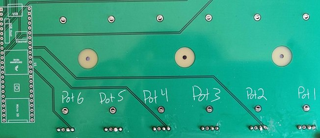
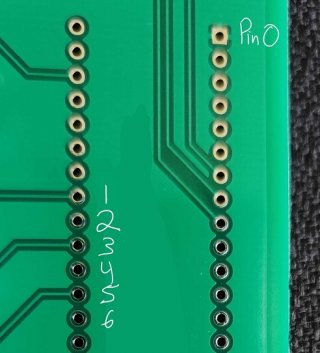
I just got some new PCBs in and have run into an odd scenario that I have not experienced before. I have tried uploading photos of the annotated boards, but it keeps saying the upload has failed.
Upon receiving the PCBs, I checked all of the through hole connections to make sure that that ground planes on the front and back were correctly going to the appropriate Teensy pins and that there were no shorts. Everything checked out as good to go.
I have since soldered on some potentiometers (10k) and have run into something I have not before, and it isnt consistent either.
If the potentiometers are at full resistance, my fluke multimeter will sometimes beep as if there is a short, although there is no connection or solder bridges between the potentiometers. They are physically far enough away that a solder bridge of that type is impossible for the data traces, and where the traces lead to eventually connect to the teensy are devoid of all solder and components as they have not been installed yet: it is just the raw throughole that previously checked out as OK, so there isnt a bridge on that side of the run.
I got the boards from JLCPCB, which was a first for me, so I was initially concerned that potentially the temperature of my soldering iron ~275-285c may have melted something away (I still have not found a lead free solder that I like, although I am trying a new brand that has some silver and rosin core which has been behaving more consistently at sub 300c temps); however, if this were due to thermal damage, this would cause a short with the ground fill that surrounds the components, not the individual data traces. The traces are all separated by at least 5 inches until they converge at the teensy's location, and I have not even touched that area yet on the boards.
Is this is most likely due to the combined resistance of the potentiometers triggering the multimeter, or is there a problem that needs to be addressed? Again, it doesnt always happen if they are maxed out either, which is throwing me for a loop.
I have done multiple passes to check under my microscope, and while the flux has melted a bit between each potentiometer's mounting hole, there are not any visible bridges that I can see.


