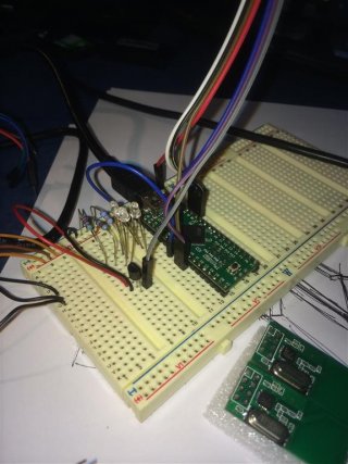
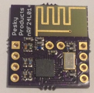
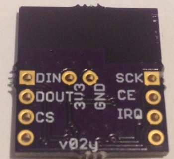
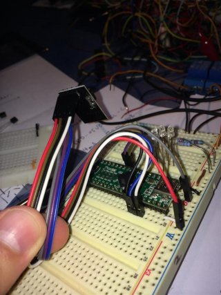
I got this module working and I wanted to share my experience so no one else has to fight with it.
I'm currently using this fork that has some extra optimizations and fixes in general:
https://github.com/TMRh20/RF24
https://github.com/TMRh20/RF24Network
This libraries work fine with Teensy 3.0, Arduino Mega and a RPi. It's also more reliable than the original versions
Getting started
NOTE: the following zip contains the original libraries, but TRMRh20 new libraries are better. Check them out too. They use the same API, and it's a direct replacement.
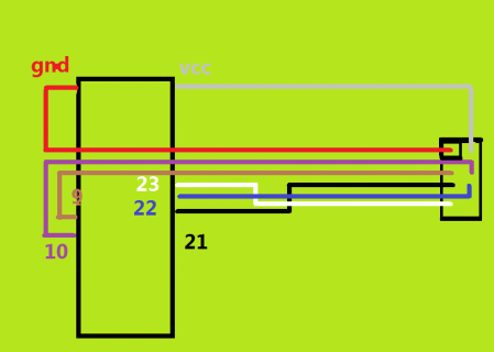
Pinout
Teensy3 -> nrf24l01
Gnd 1. GND
VCC 2. VCC
Pin 9 3. CE
Pin 10 4. CSN
Pin 13 5. SCK
Pin 11 6. MOSI
Pin 12 7. MISO
no connected 8. IRQ
Teensy++ 2.0 -> nrf24l01
Gnd 1. GND
VCC 2. VCC (*)
Pin 11 3. CE
Pin 12 4. CSN
Pin 23 7. MISO
Pin 22 6. MOSI
Pin 21 5. SCK
Pin 20 X. SS
no connected 8. IRQ
Arduino Mega -> nrf24l01
Gnd -> 1. GND
VCC -> 2. VCC (**)
48 -> 3. CE
49 -> 4. CSN
50 -> 7. MISO
51 -> 6. MOSI
52 -> 5. SCK
53 -> X. SS
no connected 8. IRQ
Teensy 3.0:
Newer versions of Teensyduino don't need any changes in the code to work. (tested on Teensyduino 1.21 test#2)
DEPRECATED:
You will get lots of errors about "printf" not working and IF_SERIAL_DEBUG not defined. Edit RF24.cpp and comment all lines that mention printf and IF_SERIAL_DEBUG (Thanks Matheus Bratfisch for the tip!). I attached a zip file with working code if you don't want to do it manually. View attachment RF24_teensy2_and_3.zip
Teensy++ 2.0 advice:
Important: set pin20 (SS) as OUTPUT
Power supply
These small modules fail if your power supply is not good enough. I have tested the following schematics on a Raspberry Pi, and two Arduino Mega (which is known to cause issues with the power supply in these modules).
Teensy++ 2.0 only:
Don't fight with voltage level conversion. Make your teensy run at 3.3V using this: http://www.pjrc.com/teensy/3volt.html
Once you do that, the 5V pin will become 3.3V, and you don't need to do anything else. Just power the nRF24L01+ from there (printed on pcb and external antennas should work out of the box).
Teensy 3.0/3.1, Raspberry pi, Arduino Mega, etc:
For the small, printed antenna, modules:
Teensy 3.0/3.1: just get your 3.3v from the teensy directly. The internal regulator is enough: https://forum.pjrc.com/threads/24343-Teensy-3-0-3-3V-pins-maximal-Current
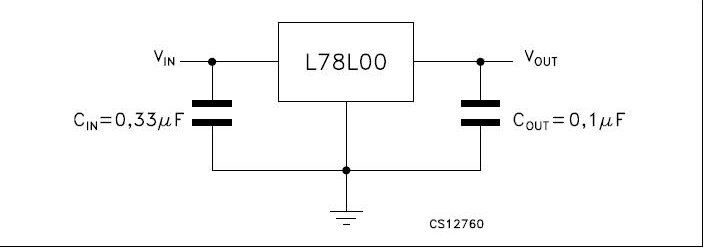
Arduinos and RaspberryPi: Try to take 5V from Rpi or Arduino and then use an L78L33 regulator to get 3.3V. The standard 78L33 design with one .33uF and one .1uF cap works fine
For the bigger modules with external detachable antennas:
Get 5V from Teensy, RPi or Arduino, then use a bigger regulator! This module consumes up to 115 mA, and the 78L33 and Teensy internal regulator are rated at 100mA max, so none of these will work.
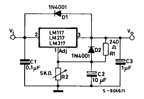
What I did: I live in Argentina and I couldn't find any decent 3.3v regulator in my city so I ended up using the LM317. It's a variable voltage regulator and you can change the output with two resistances. I verified the nrf24L01+ datasheet and when the input signals come from a 5V source (like the Arduino Mega, or the RPi), then you need to supply from 2.7 to 3.3v max.
I used R1=220 and R2=330 to get 3.125 volts from the regulator, and the module worked great. The LM317 can supply up to 1.5Amps and you only need 115mA (so it will run very very cool)
Raspberry users:
To make the examples work (ping between teensy<->raspberry) you have to make a few small changes to the librf24-bcrm examples:
1) set CE and CSN correctly (check wich raspberry you have, verify the GPIO values)
2) Make sure you set the payload size during setup. It's commented out in the RPi examples, so you will have to change that.
3) change "RF24_PA_LOW" to "RF24_PA_MAX" to make sure it's not a signal strength related issue.
4) Enable SPI from the Advanced menu, in raspi-config
PIC users:
For the love of whatever you love the most... if you get this module working with a 5V pic (specifically 18f4550), please email me! I've used level shifters for the MISO signal with no luck. I can't manage to get SPI working. (I also tried pinguino)
32 bit users (ie: teensy 3.1):
if your code works on arduinos, but it doesn't work on Teensy, you may find this post useful:
http://forum.pjrc.com/threads/24940-Teensy-3-1-nrf24l01-issue
Open source networks
tmrh20 (recommended libs): TCP/IP, RF24Network, RF24 and RF24Mesh libraries:
http://tmrh20.github.io/
Original library:
https://github.com/maniacbug/RF24
Raspberry pi port for the original lib
https://github.com/gnulnulf/RF24
Original RF24Network
http://maniacbug.github.io/RF24Network/index.html
RF24SH
http://www.matbra.com/en/code/rf24sh-internet-das-coisas/
RadioHead
http://www.airspayce.com/mikem/arduino/RadioHead/
I hope you guys find this post useful. Good Luck!
I'm currently using this fork that has some extra optimizations and fixes in general:
https://github.com/TMRh20/RF24
https://github.com/TMRh20/RF24Network
This libraries work fine with Teensy 3.0, Arduino Mega and a RPi. It's also more reliable than the original versions
Getting started
NOTE: the following zip contains the original libraries, but TRMRh20 new libraries are better. Check them out too. They use the same API, and it's a direct replacement.
- Download View attachment RF24_teensy2_and_3.zip and unzip it in "arduino_installation_dir/libraries"
- Download these example projects:View attachment pingpong test.zip
- Modify the CE and CSN pins in the code to match your pinout.
- If you are using Teensy 2 or Arduino Mega, uncomment the lines that set SS as output.
- Upload "Pingtest" to one device
- Upload "Pongtest" to the other
- Open the serial monitor in the "Pingtest" to make sure the other device is replying to your packets
Pinout
Teensy3 -> nrf24l01
Gnd 1. GND
VCC 2. VCC
Pin 9 3. CE
Pin 10 4. CSN
Pin 13 5. SCK
Pin 11 6. MOSI
Pin 12 7. MISO
no connected 8. IRQ
Teensy++ 2.0 -> nrf24l01
Gnd 1. GND
VCC 2. VCC (*)
Pin 11 3. CE
Pin 12 4. CSN
Pin 23 7. MISO
Pin 22 6. MOSI
Pin 21 5. SCK
Pin 20 X. SS
no connected 8. IRQ
Arduino Mega -> nrf24l01
Gnd -> 1. GND
VCC -> 2. VCC (**)
48 -> 3. CE
49 -> 4. CSN
50 -> 7. MISO
51 -> 6. MOSI
52 -> 5. SCK
53 -> X. SS
no connected 8. IRQ
Teensy 3.0:
Newer versions of Teensyduino don't need any changes in the code to work. (tested on Teensyduino 1.21 test#2)
DEPRECATED:
You will get lots of errors about "printf" not working and IF_SERIAL_DEBUG not defined. Edit RF24.cpp and comment all lines that mention printf and IF_SERIAL_DEBUG (Thanks Matheus Bratfisch for the tip!). I attached a zip file with working code if you don't want to do it manually. View attachment RF24_teensy2_and_3.zip
Teensy++ 2.0 advice:
Important: set pin20 (SS) as OUTPUT
Power supply
These small modules fail if your power supply is not good enough. I have tested the following schematics on a Raspberry Pi, and two Arduino Mega (which is known to cause issues with the power supply in these modules).
Teensy++ 2.0 only:
Don't fight with voltage level conversion. Make your teensy run at 3.3V using this: http://www.pjrc.com/teensy/3volt.html
Once you do that, the 5V pin will become 3.3V, and you don't need to do anything else. Just power the nRF24L01+ from there (printed on pcb and external antennas should work out of the box).
Teensy 3.0/3.1, Raspberry pi, Arduino Mega, etc:
For the small, printed antenna, modules:
Teensy 3.0/3.1: just get your 3.3v from the teensy directly. The internal regulator is enough: https://forum.pjrc.com/threads/24343-Teensy-3-0-3-3V-pins-maximal-Current
Arduinos and RaspberryPi: Try to take 5V from Rpi or Arduino and then use an L78L33 regulator to get 3.3V. The standard 78L33 design with one .33uF and one .1uF cap works fine

For the bigger modules with external detachable antennas:
Get 5V from Teensy, RPi or Arduino, then use a bigger regulator! This module consumes up to 115 mA, and the 78L33 and Teensy internal regulator are rated at 100mA max, so none of these will work.
What I did: I live in Argentina and I couldn't find any decent 3.3v regulator in my city so I ended up using the LM317. It's a variable voltage regulator and you can change the output with two resistances. I verified the nrf24L01+ datasheet and when the input signals come from a 5V source (like the Arduino Mega, or the RPi), then you need to supply from 2.7 to 3.3v max.
I used R1=220 and R2=330 to get 3.125 volts from the regulator, and the module worked great. The LM317 can supply up to 1.5Amps and you only need 115mA (so it will run very very cool)

Raspberry users:
To make the examples work (ping between teensy<->raspberry) you have to make a few small changes to the librf24-bcrm examples:
1) set CE and CSN correctly (check wich raspberry you have, verify the GPIO values)
2) Make sure you set the payload size during setup. It's commented out in the RPi examples, so you will have to change that.
3) change "RF24_PA_LOW" to "RF24_PA_MAX" to make sure it's not a signal strength related issue.
4) Enable SPI from the Advanced menu, in raspi-config
PIC users:
For the love of whatever you love the most... if you get this module working with a 5V pic (specifically 18f4550), please email me! I've used level shifters for the MISO signal with no luck. I can't manage to get SPI working. (I also tried pinguino)
32 bit users (ie: teensy 3.1):
if your code works on arduinos, but it doesn't work on Teensy, you may find this post useful:
http://forum.pjrc.com/threads/24940-Teensy-3-1-nrf24l01-issue
Open source networks
tmrh20 (recommended libs): TCP/IP, RF24Network, RF24 and RF24Mesh libraries:
http://tmrh20.github.io/
Original library:
https://github.com/maniacbug/RF24
Raspberry pi port for the original lib
https://github.com/gnulnulf/RF24
Original RF24Network
http://maniacbug.github.io/RF24Network/index.html
RF24SH
http://www.matbra.com/en/code/rf24sh-internet-das-coisas/
RadioHead
http://www.airspayce.com/mikem/arduino/RadioHead/
I hope you guys find this post useful. Good Luck!
Last edited:


