I've been working on this as a tangent, and it's time for me to get some feedback (and help) if anyone is interested. Here goes.
Note: This is not a finished/working project, but rather a work-in-progress.
Background and rationalle
What is it?
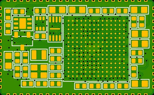
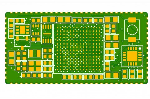
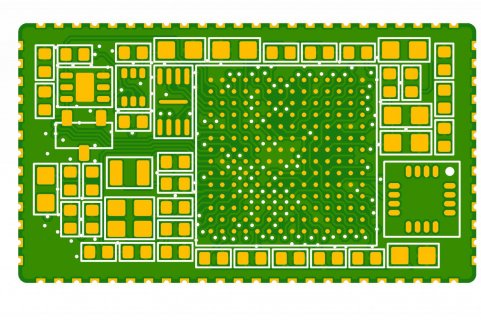
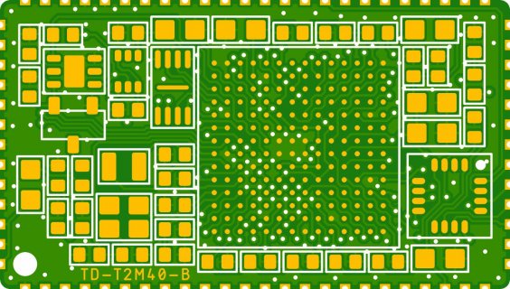
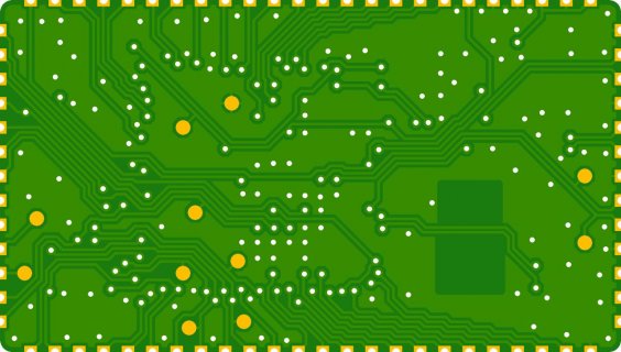
What does it look like?
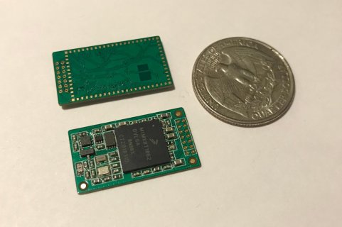
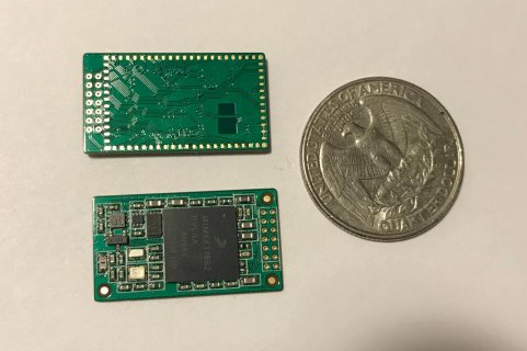
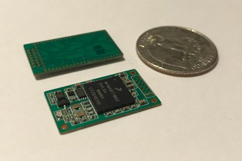
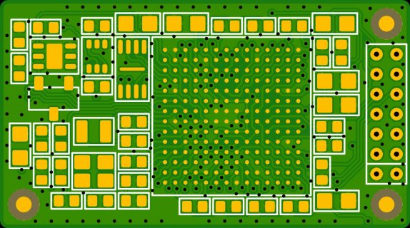
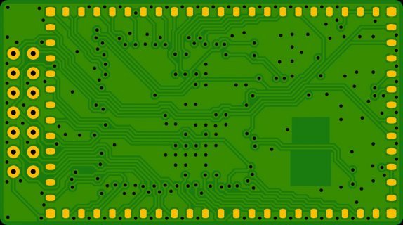
This is a first prototype of the assembled board.
How do you program it?
The theory here is that you would do one of the following:
Prototype programmers
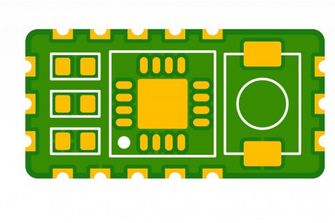
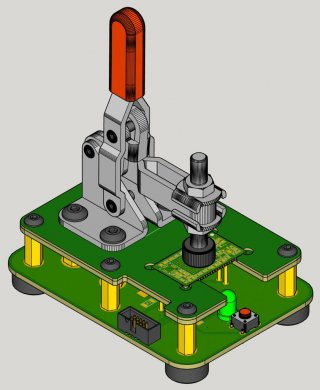
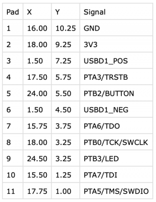
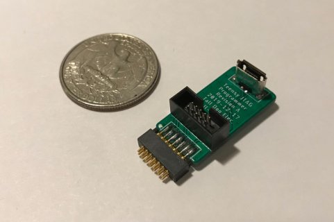
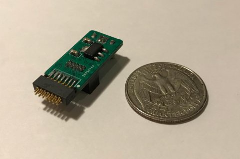
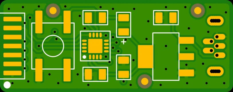
Here's the first one, a JTAG/SWD adapter. This routes the JTAG/SWD pins from a standard 0.05" header to the pogo pin array. It also has a USB port and a 5V to 3.3V regulator to power the board.
Here's the next one, a PJRC bootloader adapter. Similar to the one above, it uses USB and a regulator for power. It holds the MKL02 chip with the PJRC proprietary bootloader and has a programming button. To the Teensy loader software, this setup would look like a regular Teensy 4.0. This bootloader chip isn't available for purchase yet, and hasn't even been programmed for use with blank i.MX RT1062 chips yet anyway, so I haven't assembled one of these yet. See: https://forum.pjrc.com/threads/57132-Bootloader-Chip-For-Teensy-4-0?p=221811&viewfull=1#post221811
Problems
Programming this thing using JTAG is harder than I thought. I don't have much experience in this area, so it's possible (likely even) that I'm missing something big or making a stupid mistake. I'm used to using JTAG or SWD to program STM32 chips using an Olimex ARM-USB-OCD-H and OpenOCD. This is (relatively) straightforward. So, I thought, "Great, the i.MX RT1062 supports JTAG, so I'll do the same thing!" Except that OpenOCD doesn't seem to include any scripts for the i.MX RT1062. It does say that it has Cortex-M7 (aka ARMv7-M? Is this the exactly the same thing?) support. OpenOCD is not simple, and I'm not an embedded hardware engineer, so I haven't gotten very far on this front. Basically a lot of "Oh, I'll try this command" over and over with no results.
On page 189 of the "i.MX RT1060 Processor Reference Manual, Rev. 0, 08/2018" we have this:

Which leads me to think that the OpenOCD TAP ID for this chip should be 0x088c501d (assuming the underscore in "088C_501Dh" means absolutely nothing, and the lowercase "h" means "this is a hex string", both of which I could be wrong about).
So, needless to say, I haven't been able to get OpenOCD to communicate with the prototype board yet. The documentation for OpenOCD and the i.MX RT1062 chip pretty quickly leads me into a soup of unfamiliar three-and-four-letter-acronyms (TAP, DAP, ETM, ITM, TPIU, CTI, FPB) and I start to lose my mind (or feel like I need to go back to school for this stuff).
Next steps and questions
That's all for now. All the files are up on GitHub (https://github.com/loglow/T2M) if you want to check them out. They're not licensed yet, so please just let me know if you're wanting to use them for any derivative work. Eventually, once this project is either working or abandoned, I'll select a free/open license for them.
Any questions or thoughts or assistance is more than welcome.
Dan
Note: This is not a finished/working project, but rather a work-in-progress.
Background and rationalle
- The Teensy (especially the 4) is very powerful and can be used as the core of many different devices.
- The Teensy has an existing Arduino-compatible codebase and a strong community.
- Existing Teensy boards represent a compromise between size and usability, namely they're breadboard-friendly.
- Teensy boards are embeddable, but there are some drawbacks:
- They require pin headers to mount and through-hole assembly.
- This adds some extra height to the final assembly.
- The bootloader adds expense and size, and it may not be necessary in some embedded situations.
- If bottom Teensy pins are needed, mounting gets even more complex (and expensive).
- How small can we make an embeddable board that's fully Teensy-compatible?
- The Teensy would be used for prototyping, and then an embeddable module like this could be used in a manufactured device.
- This way we don't need to reinvent the wheel going from a prototype to a final product.
- If firmware needs to be updated by the user, we can integrate a PJRC bootloader chip sitting next to the module (maybe even as it's own sub-module?)
- This design was somewhat inspired by Sparkfun's "Creating Artemis" article: https://www.sparkfun.com/news/3122
What is it?
- This is a tiny (26 x 14.5 mm) board designed to be embedded.
- Surface-mount via reflow only, pads are on the bottom.
- Should be fully compatible with Teensy 4.0 code.
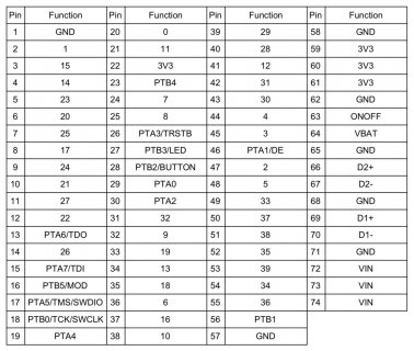
- All Teensy 4.0 pins are available.
- Does not have a bootloader chip on-board.
- Bootloader chip connections (and SWD/JTAG) are broken out for debug/flashing as 2x7 0.05" pogo pads (on top and bottom).
- Open-source design, so others can learn, modify, and benefit.
What does it look like?
This is a first prototype of the assembled board.


How do you program it?
The theory here is that you would do one of the following:
- Program it before assembly (PCBA manufacturer pre-programs the i.MX RT1062 chip (and the flash memory chip too?)).
- Program it after assembly using a custom pogo-pin fixture/jig.
- Program it after assembly (or final installation) using a pogo-pin programmer containing a PJRC bootloader chip (see below).
- Program it after assembly (or final installation) using a pogo-pin programmer/adapter connected to a JTAG/SWD device (see below).
- Program it after installation (in the field) using a PJRC bootloader chip (and a USB jack) installed next to it permanently.
Prototype programmers
Here's the first one, a JTAG/SWD adapter. This routes the JTAG/SWD pins from a standard 0.05" header to the pogo pin array. It also has a USB port and a 5V to 3.3V regulator to power the board.


Here's the next one, a PJRC bootloader adapter. Similar to the one above, it uses USB and a regulator for power. It holds the MKL02 chip with the PJRC proprietary bootloader and has a programming button. To the Teensy loader software, this setup would look like a regular Teensy 4.0. This bootloader chip isn't available for purchase yet, and hasn't even been programmed for use with blank i.MX RT1062 chips yet anyway, so I haven't assembled one of these yet. See: https://forum.pjrc.com/threads/57132-Bootloader-Chip-For-Teensy-4-0?p=221811&viewfull=1#post221811

Problems
Programming this thing using JTAG is harder than I thought. I don't have much experience in this area, so it's possible (likely even) that I'm missing something big or making a stupid mistake. I'm used to using JTAG or SWD to program STM32 chips using an Olimex ARM-USB-OCD-H and OpenOCD. This is (relatively) straightforward. So, I thought, "Great, the i.MX RT1062 supports JTAG, so I'll do the same thing!" Except that OpenOCD doesn't seem to include any scripts for the i.MX RT1062. It does say that it has Cortex-M7 (aka ARMv7-M? Is this the exactly the same thing?) support. OpenOCD is not simple, and I'm not an embedded hardware engineer, so I haven't gotten very far on this front. Basically a lot of "Oh, I'll try this command" over and over with no results.
On page 189 of the "i.MX RT1060 Processor Reference Manual, Rev. 0, 08/2018" we have this:

Which leads me to think that the OpenOCD TAP ID for this chip should be 0x088c501d (assuming the underscore in "088C_501Dh" means absolutely nothing, and the lowercase "h" means "this is a hex string", both of which I could be wrong about).
So, needless to say, I haven't been able to get OpenOCD to communicate with the prototype board yet. The documentation for OpenOCD and the i.MX RT1062 chip pretty quickly leads me into a soup of unfamiliar three-and-four-letter-acronyms (TAP, DAP, ETM, ITM, TPIU, CTI, FPB) and I start to lose my mind (or feel like I need to go back to school for this stuff).
Next steps and questions
- Big-picture: Does this project make sense, on a technical/logistical/ethical/spiritual level? Do you see a utility in these boards? Are they technically feasible, or am I making a big incorrect assumption (for example, that the MKL20 isn't necessary aside from flashing the i.MX RT1062)? Is there any market for these? Does Paul like/hate this idea? I don't exactly want to cut PJRC out of the loop here, but someone could make an argument that this is sort of doing just that (although I don't think it is exactly, but it's complicated). I haven't invested much time or money into this, so I'm pretty flexible with it.
- Small-picture: Assuming I haven't made any show-stopping assumptions, the next step is to actually get the chip initialized/programmed via JTAG or SWD. Is this even possible with OpenOCD? There's other hardware (like the LPC-Link2) and other software (like MCUXpresso) that might work and/or be required here perhaps? I have neither of these tools on-hand, at the moment.
- I could give up on JTAG/SWD for now and just wait for Paul/PJRC to release the updated MKL02 bootloader for the Teensy 4.0. Then I could assemble the MKL02 programmer and see if any of the assembled boards actually work, and if they do, I could begin testing them.
That's all for now. All the files are up on GitHub (https://github.com/loglow/T2M) if you want to check them out. They're not licensed yet, so please just let me know if you're wanting to use them for any derivative work. Eventually, once this project is either working or abandoned, I'll select a free/open license for them.
Any questions or thoughts or assistance is more than welcome.
Dan


