Teensy 2.0 interrupt

Status
Not open for further replies.

Fluxia

Member
Hello

I am just learning to code microcontrollers and my current project is to build a MIDI controller using a teensy 2.0. I need at least six pins with interrupt capability as I am using three encoders. I have started prototyping with an arduino and I was able to make it work by using the arduino library "EnableInterrupt.h", which allows me to use any pin as an interrupt. So with the arduino (UNO) I have had no problems but I cannot figure out how to do this with a teensy, or whether it is possible at all.

Any help would be appreciated.

Cheers!
 
Thanks for your reply. If I understand it correctly the table shows that I can only use 4 pins with interrupt capability, but I need 6. If use only one interrupt capable pin for two encoders this would give me good performance rather than best performance, which is still good enough probably, but I was just wandering if there was a library that could achieve the same result with teensy as the enable interrupt library does with arduino uno.
 
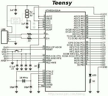
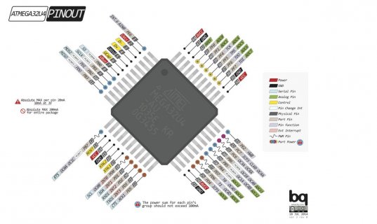
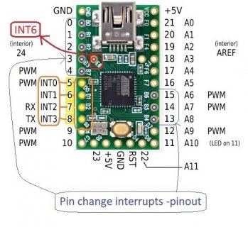
Just to let you know the Teensy 2.0 (ATMega32U4) has 4 INT External Interrupt and 8 PCINT Pin Change Interrupts.
schematic2.gif
ATmega32U4.jpg

Add Interrupt pins to Teensy 2.0
 
Last edited:
Pin change interrupts
There are two ways you can detect external events on pins. The first is the special "external interrupt"on the Atmega328-(Arduino UNO) pins, D2 and D3. These general discrete interrupt events, one per pin. You can get to those by using attachInterrupt for each pin. You can specify a rising, falling, changing or low-level condition for the interrupt.
However there are also "pin change" interrupts for all pins (on the Atmega328, not necessarily all pins on other processors). These act on groups of pins (D0 to D7, D8 to D13, and A0 to A5). They are also lower priority than the external event interrupts.
 
Thank you Chris very helpful. Are you aware of any library that exist to simplify using the pin change interrupts? I have only just started learning arduino two months ago so I think that I may struggle without a library to simplify the use of them. As I said, I have been able to use the arduino ones without problem (with the enable interrupt library).
Also I am not sure I am using the attachinterrupt function properly for the teensy. It is straightfoward on the arduino but when I upload the same code on the teensy (just changing the pin number (INT number are the same 0 and 1) it does not work. It will compile and upload no problem but the encoder does not work.
I have now used the encoder library example for the Teensy and I didn't use the attachinterrupt function, I suppose that this is all dealt by the encoder library? the instructions on the example state:

// Change these two numbers to the pins connected to your encoder.
// Best Performance: both pins have interrupt capability
// Good Performance: only the first pin has interrupt capability
// Low Performance: neither pin has interrupt capability

So I suppose that I am using the external interrupts by using this example code?....
 
The Teensy encoder library automatically uses interrupts if available. If performance is provable such an issue that you need more interupts you should probably look at a more capable CPU. Unless you are making 10s of thousands of units it is very easy to spend more time and effort getting code to run on minimal hardware than spending a couple more dollars on more capable hardware.

For three hand operated encoders your T2 is probably fine. The need for high performance comes in when the encoder is being driven mechanically as a position or RPM sensor. In your case if the user flicks the dial and the count comes up short they just keep turning until they do reach the set point they needed.
 
It will compile and upload no problem but the encoder does not work.

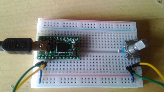
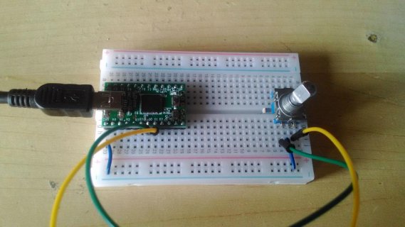
Generally the way we work here involves showing the complete non-working code. "Complete" means anyone can copy it into Arduino and upload it to their board, to recreate the problem. That is assuming they've got an encoder wired up, and generally when you show such code you should be clear about how you've wired up your hardware. Photos are the easiest and best way.

We can talk at length about how the library is designed and alternate ways it might be made, but if you want actual help with getting things working (which should be able to work), you need to show what you're actually doing.
 
Thank you both. I have now been able to make the encoder work using the attachinterrup function. Not sure what happened yesterday as I used exactly the same code (just rewired my breadboard...), and ... yes probably in my case polling may even be fast enough for my encoder to do their job. It 's also good to know what are the applications that really need interrupts. However while I am working on this project I also I wanted to learn how to properly use interrupts so may be helpful to clarify these issues.
I have pasted below the code I am using. I have commented out the enableinterrupt function and the code as it is works well both with arduino and Teensy (clearly I need to change the variables outputA and outputB to make them match the right pin). However, using the enableinterrup function only works with arduino. If I try to use it with the teensy it will not let me compile. Now if Teensy has PCINT in the pins PB0 to PB7 why would this not work? I suppose I would need to use the values 0 and 1 for outputA and outputB as they would correspond to PB0 and PB1?
I have also attached a pic of my breadboard connections when using pin 0, 1 and 5,6.P_20180325_142554.jpgP_20180325_142525.jpg

Code:
//#include <EnableInterrupt.h>

#define outputA 5
#define outputB 6

int counter = 0;
int aState;
int aLastState;

void setup() {

  attachInterrupt(outputA, encoder, CHANGE);
  attachInterrupt(outputB, encoder, CHANGE);

//    enableInterrupt(outputA, encoder, CHANGE);
//    enableInterrupt(outputB, encoder, CHANGE);

  pinMode (outputA, INPUT_PULLUP);
  pinMode (outputB, INPUT_PULLUP);

  Serial.begin (9600);

  aLastState = digitalRead(outputA);                         // Reads the initial state of the outputA
}

void loop() {

}

void encoder () {

  aState = digitalRead(outputA);                            // Reads the current "state" of the Encoder

  if (aState != aLastState) {                              // If the previous state and the current state of outputA are different a pulse occurred

    if (digitalRead(outputB) != aState) {                   // If the outputB state is different from outputA the Encoder is rotating clockwise
      counter ++;
    }
    else {                                                // otherwise the Encoder is rotating anticlockwise
      counter --;
    }
    Serial.println(counter);
  }
  aLastState = aState; // If the output_B state is different from OutputA it means that the Encoder is rotating clockwise...
}
 
Last edited:
Ok I was wrong on the INT External Interrupts available, there is actually 5 External Interrupts on Teensy 2.0
Unfortunately you need to access the interior pin 24, INT6 (marked in red color).

External Interrupts (INT)
Board Digital Pins Usable For Interrupts :
Uno, Nano, Mini, Atmega328-based 2, 3
Micro, Leonardo, Atmega32u4-based 0, 1, 2, 3, 7
Teensy 2.0, Atmega32u4-based 5, 6, 7, 8, 24 --- (5 INT) External Interrupts
Teensy 2.0 INT pins.jpg
 
Give this a try:
NOTE: Completely untested code since i don't have Teensy 2.0
Example: Pin change interrupt test, setup for PIN 0.
Code:
// Pin change interrupt test PCINTn
// Uno Atemga Atmega328-based (PCINT0_vect,8-9-10-11-12-13),(PCINT1_vect, A0-A5),(PCINT2_vect, D0-D7)
// Teensy 2.0 Atmega32u4-based (PCINT0_vect, PINs 0-1-2-3-4-13-14-15) --- (8 PCINT) Pin Change Interrupts

byte Debug_led = LED_BUILTIN; // TEENSY 2.0 LED on pin 11
byte PinChangeI_pin = 0; // USE ONLY PINs 0-1-2-3-4-13-14-15 on Teensy 2.0.

// The elapsedMillis feature is built into Teensyduino.
// For non-Teensy boards, it is available as a library.
elapsedMillis sinceLed;

// --------- Pin change interrupt setup ------------------
// Install Pin change interrupt for a pin, can be called multiple times
void PciSetup(byte pin)
{
  *digitalPinToPCMSK(pin) |= bit (digitalPinToPCMSKbit(pin));  // enable pin
  PCIFR  |= bit (digitalPinToPCICRbit(pin)); // clear any outstanding interrupt
  PCMSK0 |= bit (digitalPinToPCICRbit(pin)); // Enable Mask
  PCICR  |= bit (digitalPinToPCICRbit(pin)); // Enable interrupt
}

void setup() {
  // put your setup code here, to run once:
  Serial.begin (9600);
  pinMode(Debug_led, OUTPUT);

  pinMode(PinChangeI_pin, INPUT_PULLUP);
  // USE ONLY PINs 0-1-2-3-4-13-14 or 15 on Teensy 2.0.
  PciSetup(PinChangeI_pin); // Enable Pin Change Interrupt for pin...
}

void loop() {
  // put your main code here, to run repeatedly:
  if (sinceLed >= 250) { // run every 0.nnn ms
    //sinceLed = 0; // reset since
    digitalWrite(Debug_led, LOW);
  }
}

// ---------------- ISR ------------------
// Pin change interrupt.
// USE ONLY PINs 0-1-2-3-4-13-14 or 15 on Teensy 2.0.
ISR (PCINT0_vect) //
{
  // TODO, responsibility of the single PinChange interrupt service routine.
  // determine Which pins changed, and in what direction
  sinceLed = 0; // reset since
  digitalWrite(Debug_led, HIGH);
}
 
I have tried it and the led lighten up when changing the state of the pin 0 with a push button but it's not very consistent. Not sure that I am actually using it appropriately but thank you. Now I now where the PCINT are, maybe at some point I will be able to use them :)
Where did you find about INT 6 on pin 24? and is't it strange that they call it INT6 (if there are no INT4 and INT5)?
 
Status
Not open for further replies.
Back
Top