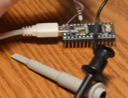
Teensy 3.1 PWM output jitters

Hi all,

I am trying to use a Teensy 3.1 running at 72Mhz to generate some quality PWM output at to precisely control 2 large brushed motors.

I am using the below code, following this article.

Code:
void setup(void)
{
  analogWriteFrequency(21, 35156.25); //resolution will be 10 bit: 0 - 1023. See also: https://www.pjrc.com/teensy/td_pulse.html
  analogWriteResolution(10); //10 bit: 0 - 1023
  analogWrite(21, 511.5);
}
void loop(void)
{
}

This code is supposed to generate a 50% duty cycle PWM signal at 35156.25 Hz on pin 21.

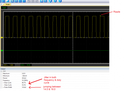
However, the kind of PWM output I am getting is not as good as I wanted, and not good enough for the application. There are a few observations as follows (please also see attached photos):

1. The max voltage is 3.61V, not 3.3V. How come? I need this to be an exact value to feed the motor driver

2. Pulse width, frequency and duty cycle keep jittering between 2 values. For instance, pulse width keeps jumping between 14.0uS and 16.0uS, while duty cycle + keeps jumping between 50% and 53.3%, which is not good for the motor.

So are there any other ways to generate better PWM output? Anything can be improved in my setting?

Thanks in advance.
Dave
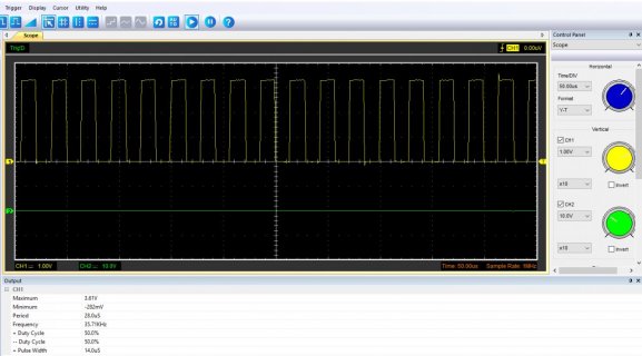
image1.jpg
image2.png
 
Last edited:
I am getting much less jitter by lowering down the frequency all the way to 1098.632 Now duty cycle is quite stable, it's just jumping between 50.1% and 49.9%, which is quite fine. But this frequency is kind of low for my motor driver. Doubling the frequency, which is decent for the driver will give 49.8%-50.2% jittering, which is ok. But I am still interested in knowing if even better output can be achieved.

Dave
 
Last edited:
Running your sketch requesting 35156.25 hz on T3.2 @96mhz, my analyzer (sampling at 32mhz) gets 35.1648khz +/- 0.2%, duty 49.890% +/- 0.5% (same @72mhz). Perhaps your measurement device is causing the discretization error?

FWIW, using 512 in the analogWrite() gives duty of 50.000% +/- 0.5%

(You could choose a frequency that is a multiple of prescaler/MOD of FTM PWM timer to get output frequency closer to requested frequency. For example, T3.2@96mhz requesting 35164 hz, my analyzer shows 35.1648 khz +/- 0.2% )
 
Last edited:
Running your sketch requesting 35156.25 hz on T3.2 @96mhz
According to the table in the article, the ideal speed for 35156.25 hz is 72Mhz?

Perhaps your measurement device is causing the discretization error
Could be, as I am using a cheap USB Oscilloscope from China, connecting to the laptop.

Right now I think I can make do with this (@72Mhz):

analogWriteFrequency(21, 2197.265); //resolution will be 14 bit: 0 - 16384. See also: https://www.pjrc.com/teensy/td_pulse.html
analogWriteResolution(14); //10 bit: 0 - 16384
analogWrite(21, 8192);

This give a freq of 2193 - 2203 (desired 2197.265 +/- 0.2%)
Duty cycle: 49.8% - 50.2% (desired duty +/- 0.4%)

My motor driver recommend a PWM freq higher than 1000 Hz so I hope 2197.265 is good enough. But I also want to try increasing and observe with a better oscilloscope that I can borrow.

Do you know the real resolution of this PWM output?
 
Last edited:
Also I am concerned about the peak voltage of the PWM signal, it's around 3.51V instead of 3.3V. Is there some way (such as using Analog reference, which I can't find on the Teensy 3.2) to make sure it's 3.3V?
 
Also I am concerned about the peak voltage of the PWM signal, it's around 3.51V instead of 3.3V. Is there some way (such as using Analog reference, which I can't find on the Teensy 3.2) to make sure it's 3.3V?

i'm pretty sure your pin output is close to 3.3v. you could use a voltmeter with PWM duty cycle 100% (or just digitalWrite(pin,HIGH)). Confidence in your "cheap USB Oscilloscope from China" is diminishing ... :(

for T3.2@72mhz analogWriteFrequency(21, 2197.265); my analyzer (32mhz sample rate) shows 2197.199 hz +/- 0.1%, duty 50.000% +/- 0.1%

if you look at the FTM registers, the PWM output should be 36mhz/16384
 
Last edited:
Anything can be improved in my setting?

Yes, your oscilloscope! Whatever you're using is truly horrible. Which scope is that?

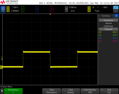
Here's a jitter test. I let this run for a few minutes with infinite display persistence.

file.png

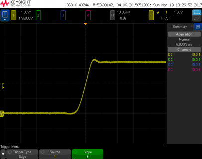
You can see the slight overshoot above 3.3V here. That's due to the inductance of the ground lead clip. Overshoot, though not normally as narrow, can also occur if probes aren't properly compensated for your scope's input capacitance. The probes on my scope are.

Here's a closer look at the overshoot. Keep in mind I have only 200 MHz bandwidth here.

file.png

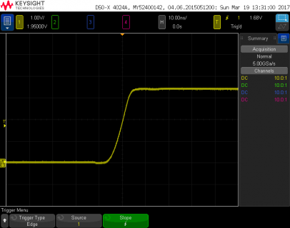
Here is the exact same signal, but this time I took the convenient clip and ground lead off my scope probe. I touched the probe point right to the pin on Teensy, and I wrapped a piece of #22 solid wire around the probe's ground shied and ran it right to the shell of the USB connector.

file.png

This is a classic well known issue with scope probes, where you see overshoot with fast edges if your measurement includes ground inductance.

Here's a photo of the how I made the 2nd measurement. (admittedly blurry.... tough to hold the camera still with the other hand awkwardly holding the scope probe)

probe.jpg

You can see the unused ground lead and clip in the front. No matter how good your scope is, the extra inductance from a ground clip adds overshoot. It's not a real signal. This is a very well known artifact of oscilloscope probes. Those clips are really convenient, but they cause issues with higher bandwidth (over about 20 MHz). This is the main reason all scopes have a bandwidth limit button!

But your scope is suffering from much more than just inductance on its probes. According to your software, a waveform with very low jitter is changing by about 2 us. It seems unimaginable that an oscilloscope would sample at only 500 kSamples/sec. Then again, your screenshot says in the lower right corner a sample rate is only 1 MHz. Maybe that's divided between the 2 channels, so each is resolving only to the nearest 2 microseconds?

The bottom line is your oscilloscope is pretty much worthless for this sort of work. You can't possibly make valid conclusions about jitter with such a low sample rate.
 
Yes, your oscilloscope is the problem. Teensy is producing a very stable waveform. It only appears to jump back and forth because your oscilloscope is bad.
 
Yes, your oscilloscope! Whatever you're using is truly horrible. Which scope is that?

This is a classic well known issue with scope probes, where you see overshoot with fast edges if your measurement includes ground inductance.

You can see the unused ground lead and clip in the front. No matter how good your scope is, the extra inductance from a ground clip adds overshoot. It's not a real signal. This is a very well known artifact of oscilloscope probes. Those clips are really convenient, but they cause issues with higher bandwidth (over about 20 MHz). This is the main reason all scopes have a bandwidth limit button!

But your scope is suffering from much more than just inductance on its probes. According to your software, a waveform with very low jitter is changing by about 2 us. It seems unimaginable that an oscilloscope would sample at only 500 kSamples/sec. Then again, your screenshot says in the lower right corner a sample rate is only 1 MHz. Maybe that's divided between the 2 channels, so each is resolving only to the nearest 2 microseconds?

The bottom line is your oscilloscope is pretty much worthless for this sort of work. You can't possibly make valid conclusions about jitter with such a low sample rate.

Wow, I just can't thank you enough for taking all the time to share and to prepare those photos. Now I believe that it's should be my crappy scope and not the teensy. Will learn a bit more about scopes and maybe I will get a good one to try again!

Thanks again for sharing the knowledge.
 
Sample rate lower than the bandwidth is terrible. Sample rates need to be at least twice the bandwidth just to avoid Nyquist aliasing! Even low budget scopes like Rigol use 250 MSample/sec (1 GSample/sec divided by 4 channels) when implementing 100 MHz bandwidth. Good quality scopes have samples rates at 4X or 5X the analog bandwidth.

Maybe this sort of scope can be used for some limited troubleshooting, but you really can't trust it to make any sort of accurate measurement. In fact, you can expect it to give you wrong results in many circumstances.
 
Last edited:
Back
Top