Teensy 4.0 SDIO CLK (intermittent)

domingo

Well-known member
Hello,

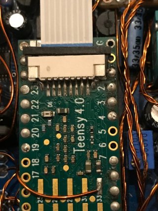
I added a socket, flex cable and SD card socket to the Teensy 4.0, to record audio files. Normally I'd have used the Teensy 4.1, but it is unfortunately too big for my PCB.

Problem is that every ~second I get an interruption, like a tik-tik-tik sound, only while recording. I traced it down to the SDIO CLK pin. If touch I that pin with a wire the noise increases. If I touch it with a shorted capacitor it increases even more (!)–just experimenting. The tik-tik is constant and it doesn't vary with CPU speed. It doesn't change either adding the following line to decrease the pin's current (to my understanding):
Code:
IOMUXC_SW_MUX_CTL_PAD_GPIO_SD_B0_01 = 0x8;

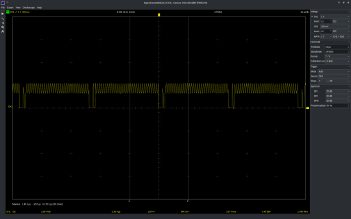
I measured the SDIO CLK signal with an oscilloscope and it shows some intermittency. But CLK speed is 1.5MHz. Isn't that too low and my scope messing around?

Anyways. Any clues on how to solve this? Or what is causing it? I wonder if the clock is being interrupted for some (electronic) reason, like stray capacitance. Or rather the clock itself is radiating HF into the analog audio path, but I doubt it. My ADC is not the Teensy Shield, but a DIY custom PCB board I made myself. But it seems more like a problem between the Teensy-SD connection to me.

Salutations,
Domingo
 

Attachments

  • sdio_clk_pull-act_150MHz.png
    sdio_clk_pull-act_150MHz.png
    133.5 KB · Views: 18
  • IMG_5205.jpg
    IMG_5205.jpg
    205 KB · Views: 16
Do you have a Teensy 4.1?

Probably best to first get your software working on the known-good hardware of Teensy 4.1. Then after you have known good code recording flawless files, go back to the custom hardware.

Trying to troubleshoot custom built hardware running code that hasn't been proven on good hardware is a recipe for frustration.
 
Thanks Paul! I thought I had a T4.1 but it doesn't start.. now I remember I fried it some time ago :/
It's a good advice, I'll need some time to get another one and fit it somehow for a test at least.

You made me think that it might be a software related issue as well. Now I realised that the interruption changes in rhythm if I modify the audio buffer const size_t sz in the code (below). Is there anything visibly wrong here that cause the problem? Anyways getting pockets ready for a T4.1 to try.

🤖

Code:
//Use Audio Library (SD Buffered)
//https://github.com/h4yn0nnym0u5e/Audio/tree/feature/buffered-SD

#include <Audio.h>
#include <Wire.h>
#include <SPI.h>
#include <SD.h>
#include <Bounce.h>
#include <SerialFlash.h>
#include <EEPROM.h>

AudioInputI2S            i2s1;           //xy=220,698
AudioInputUSB            usb2;           //xy=223,853
AudioPlayWAVstereo       playWAVstereo1;     //xy=244,609
AudioRecordWAVstereo     recordWAVstereo1; //xy=321,98
AudioMixer4              mixer1;         //xy=468,691
AudioMixer4              mixer2;         //xy=467,769
AudioMixer4              mixer3;         //xy=470,854
AudioMixer4              mixer4;         //xy=482,934
AudioAnalyzePeak         peak1;          //xy=603,576
AudioOutputI2S2          i2s2_1;         //xy=643,732
AudioOutputUSB           usb1;           //xy=649,914
AudioConnection          patchCord1(i2s1, 0, mixer1, 0);
AudioConnection          patchCord2(i2s1, 1, mixer2, 0);
AudioConnection          patchCord3(i2s1, 0, mixer3, 0);
AudioConnection          patchCord4(i2s1, 1, mixer4, 0);
AudioConnection          patchCord5(playWAVstereo1, 0, mixer1, 2);
AudioConnection          patchCord6(playWAVstereo1, 1, mixer2, 2);
AudioConnection          patchCord7(usb2, 0, mixer1, 1);
AudioConnection          patchCord8(usb2, 1, mixer2, 1);
AudioConnection          patchCord9(mixer1, 0, i2s2_1, 0);
AudioConnection          patchCord10(i2s1, 0, recordWAVstereo1, 0);
AudioConnection          patchCord11(i2s1, 0, peak1, 0);
AudioConnection          patchCord12(mixer2, 0, i2s2_1, 1);
AudioConnection          patchCord13(i2s1, 1, recordWAVstereo1, 1);
AudioConnection          patchCord14(mixer3, 0, usb1, 0);
AudioConnection          patchCord15(mixer4, 0, usb1, 1);

const int pdnADC = 22;
const int pdnDAC = 1;
const int VOLUME_POT = 14;

Bounce buttonRecord = Bounce(7, 8);
Bounce buttonStop =   Bounce(9, 8);  // 8 = 8 ms debounce time
Bounce buttonPlay =   Bounce(10, 8);

#define SDCARD_CS_PIN    BUILTIN_SDCARD
#define SDCARD_MOSI_PIN  11  // not actually used
#define SDCARD_SCK_PIN   13  // not actually used

// Remember which mode we're doing
int mode = 0;  // 0=stopped, 1=recording, 2=playing

int File_Number;
int address = 10;

// The file where data is recorded
File frec;


void setup() {

  AudioMemory(12);

  pinMode(pdnADC, OUTPUT);
  delay(10);               // wait
  digitalWrite(pdnADC, HIGH);    // set the PDN on

  pinMode(pdnDAC, OUTPUT);
  delay(10);               // wait
  digitalWrite(pdnDAC, HIGH);    // set the PDN on
 
  IOMUXC_SW_PAD_CTL_PAD_GPIO_AD_B1_09 = 0x8; // MCLK
  IOMUXC_SW_PAD_CTL_PAD_GPIO_AD_B1_10 = 0x8; // LRCLK
  IOMUXC_SW_PAD_CTL_PAD_GPIO_AD_B1_11 = 0x8; // BCKL
  IOMUXC_SW_PAD_CTL_PAD_GPIO_B1_01 = 0x8; // OUT1A
  IOMUXC_SW_PAD_CTL_PAD_GPIO_B1_00 = 0x8; // IN1
  IOMUXC_SW_PAD_CTL_PAD_GPIO_EMC_04 = 0x8; // OUT2
  IOMUXC_SW_PAD_CTL_PAD_GPIO_EMC_05 = 0x8; // LRCLK2
  IOMUXC_SW_PAD_CTL_PAD_GPIO_EMC_06 = 0x8; // BCLK2
  IOMUXC_SW_PAD_CTL_PAD_GPIO_EMC_07 = 0x8; // MCLK2
  IOMUXC_SW_PAD_CTL_PAD_GPIO_B1_00 = 0x8; // IN2
  IOMUXC_SW_MUX_CTL_PAD_GPIO_SD_B0_00 = 0x8;
 // IOMUXC_SW_MUX_CTL_PAD_GPIO_SD_B0_01 = 0x8; //CLK
  IOMUXC_SW_MUX_CTL_PAD_GPIO_SD_B0_02 = 0x8;
  IOMUXC_SW_MUX_CTL_PAD_GPIO_SD_B0_03 = 0x8;
  IOMUXC_SW_MUX_CTL_PAD_GPIO_SD_B0_04 = 0x8;
  IOMUXC_SW_MUX_CTL_PAD_GPIO_SD_B0_05 = 0x8;
  IOMUXC_SW_PAD_CTL_PAD_GPIO_B1_02 = 0x8; // PIN 14


  // Configure the pushbutton pins
  pinMode(7, INPUT_PULLUP);
  pinMode(9, INPUT_PULLUP);
  pinMode(10, INPUT_PULLUP);


  // Initialize the SD card
  SPI.setMOSI(SDCARD_MOSI_PIN);
  SPI.setSCK(SDCARD_SCK_PIN);
  if (!(SD.begin(SDCARD_CS_PIN))) {
    // stop here if no SD card, but print a message
    while (1) {
      Serial.println("Unable to access the SD card");
      delay(500);
   }
  }


 // SD audio objects need buffers configuring:
  const size_t sz = 65536;
  const AudioBuffer::bufType bufMem = AudioBuffer::inHeap;
  playWAVstereo1.createBuffer(sz,bufMem);
  recordWAVstereo1.createBuffer(sz,bufMem);

  //Filename numbers
  File_Number = EEPROM16_Read(address);
  Serial.print("Actual File Number: ");
  Serial.println(File_Number);
}

void loop() {

  float vol = analogRead(VOLUME_POT);
   vol = vol / 1023;
  mixer1.gain(0, 1*vol);
  mixer2.gain(0, 1*vol);
 
  Serial.print("Digital volume is: ");
  Serial.println(vol);
  delay(250);

  // First, read the buttons
  buttonRecord.update();
  buttonStop.update();
  buttonPlay.update();

  // Respond to button presses
  if (buttonRecord.fallingEdge()) {
    Serial.println("Record Button Press");
    if (mode == 2) stopPlaying();
    if (mode == 0) startRecording();
  }
  if (buttonStop.fallingEdge()) {
    Serial.println("Stop Button Press");
    if (mode == 1) stopRecording();
    if (mode == 2) stopPlaying();
  }
  if (buttonPlay.fallingEdge()) {
    Serial.println("Play Button Press");
    if (mode == 1) stopRecording();
    if (mode == 0) startPlaying();
//    if (mode == 2) playPrevious();
  }


  // If we're playing or recording, carry on...
  if (mode == 1) {
    continueRecording();
  }
  if (mode == 2) {
    continuePlaying();
  }
}


void startRecording() {
  Serial.print("startRecording RECORD_");
  Serial.println(File_Number);
  char buffer[40];
  sprintf(buffer, "%d.wav", File_Number);
  if (SD.exists(buffer)) { 
    // The SD library writes new data to the end of the
    // file, so to start a new recording, the old file
    // must be deleted before new data is written.
    SD.remove(buffer);
  }
  frec = SD.open(buffer, FILE_WRITE);
  if (frec) {
    
patchCord9.disconnect();
patchCord12.disconnect();
delay(200);
patchCord9.connect();
patchCord12.connect();
 
  recordWAVstereo1.recordSD(buffer);
  mode = 1;
  }
}

void continueRecording() {
}


void stopRecording() {
  Serial.println("stopRecording");
  recordWAVstereo1.stop();

  patchCord9.disconnect();
  patchCord12.disconnect();
  delay(200);
  patchCord9.connect();
  patchCord12.connect();
 
  File_Number = File_Number + 1;
  EEPROM16_Write(address, File_Number);
  mode = 0;
}

void startPlaying() {
  Serial.print("startPlaying RECORD_");
  Serial.println(File_Number - 1);
 
  char buffer[40];
  sprintf(buffer, "%d.wav", File_Number - 1);
 
  playWAVstereo1.playSD(buffer);
  patchCord1.disconnect();
  patchCord2.disconnect();
  mode = 2;
}

void continuePlaying() {
  if (!playWAVstereo1.isPlaying())
  {
    Serial.println("endOfPlayback");
   patchCord1.connect();
   patchCord2.connect();
    mode = 0;
  }
}
 
void stopPlaying() {
  Serial.println("stopPlaying");
  playWAVstereo1.stop();
  patchCord1.connect();
  patchCord2.connect();
  mode = 0;
}

void EEPROM16_Write(uint8_t a, uint16_t b) {
  EEPROM.write(a, lowByte(b));
  EEPROM.write(a + 1, highByte(b));
}

uint16_t EEPROM16_Read(uint8_t a) {
  return word(EEPROM.read(a + 1), EEPROM.read(a));
}
 
That’s using my buffered play/record library, continueRecording() doesn’t need to do anything because the record object does the SD writes in an event response.

I recall from the audio guestbook thread that power / ground bounce could get into the recorded audio. Changing the buffer size does change the writing interval and hence the “tick” interval. Not a problem with a Teensy 4.1’s built in slot because the power to the SD card doesn’t go near the audio paths. SD cards can take big gulps of current while writing…

A bit of attention to keeping the SD card and audio power isolated from one another, with fat wires, good routing and decoupling, and you should hear an improvement.
 
Thank you for the info @h4yn0nnym0u5e. I listen with attention because moving to the 4.1 I would need to make quite dramatic changes to my chassis concept and PCB layout.

Would it help/work if I install a separate 3.3V VREG for the SD Card, instead of using the 3.3V provided by the SDIO pin? This separate 3.3V for SDCard would still be powered by the Li-ION battery that powers the Teensy in my case, but it might deal with those 'gulps' interfering the (digital?) audio paths I guess.
My analog audio paths have an independent power supply and my PCB has well divided sections for digital (DAC/ADC) and analog circuits. Bridged only where the converter chips are on my PCB. I can't visualize why current draw from the SDCard would then affect my analog circuits. I'll try to find more 'lost souls' and wisdom in the audio guestbook as you mentioned. 🙏
 
Please do bear in mind I'm primarily a software guy who knows just enough about hardware to be dangerous!

My contributions on the audio guestbook thread relating to this issue are around here. Various pieces of evidence seemed to stack up, including the observation you made in post #3 above that the ticking period changes with buffer size (because a bigger buffer means SD writes need to happen less often). With the 64k buffers in your example code, each write will be 32k (half a buffer), or 64 SD card sectors, or 8k samples (because you're recording stereo), and happen with a period of 8192/44100 = 0.186s.

Without knowing what you've actually done for component choice and layout it's really hard to say what will "help/work". Schematic and PCB layout will be helpful there ... words saying essentially "I think I've done it right" ... not so much. You can be pretty sure that if the audio is truly clean at the point of being captured by the ADC, no amount of variation in power draw by the SD card will affect it thereafter. I did a bit of research and it looks like they can take 100mA or more briefly during writes, which is as much as the entire Teensy CPU. Very easy to get accidentally coupled into the audio.

I took a proper look at your scope trace, and I'm pretty sure your sample rate of 24MS/s is too low to capture the SDIO clock accurately. That may not matter too much, though worth checking if you can. Possibly more interesting would be to look at the overall pattern of the clock "bursts" during an SD write, and compare to the recorded ticks. The linked post shows the effect on audio, and it appears to me to show a sector write, an inactive interval, then the remaining sectors writes with only short inactive intervals between them. If that pattern matches between the clock bursts and audio ticks, we can be sure SD writes cause audio ticks. We still won't know if it's current draw or coupling of signals, but it would show where we should be looking...
 
Thanks for the lights @h4yn0nnym0u5e !
At the moment I cannot share the system diagrams and details, but I will as soon as I can!

For now just another question. As I increase the buffer size the tik-tik-tik increases in speed. Shouldn't it be the other way around, if writes are happening less frequently?

30MS/s is the max. speed of my scope, so I guess I won't be able to see the clock signal properly. I relate it to the SDIO clock because the volume of the 'interruption' increases if I touch the pin (36 in the T4) with a wire as an antena... It's not a full interruption, but tiks at the background. Not really visible on the audio waveform when recording ambient sound, but loud enough to make the audio file unusable many times.

I'm also not a hardware or software person, I mostly fiddle around and try to make things I need work :) I use this setup to record wild tracks for film with filter effects. I designed the circuit myself, so very likely there are layout mistakes as well; just trying to gather some clues.

PD: Your library is amazing btw. I should credit it more clearly in the code.
 
For now just another question. As I increase the buffer size the tik-tik-tik increases in speed. Shouldn't it be the other way around, if writes are happening less frequently?
Yes, it should, so it’s likely not the writes. You only said “changes” the speed, so I had to guess bigger was slower, as that’s what we saw previously.
 
Yes, it should, so it’s likely not the writes.
That's a clue! Maybe it is just EMI from the 24MS/s clock polluting by nearby analog circuits, but it doesn't make much sense that it does so 'in intervals'. I assume EMI should be constant.
Also the clock speed doesn't change with changes in buffer size, right. Then why would the rate of the clock's EMI change along buffer size...:unsure:

Having series resistors across the SDIO lines helped (100-680ohm), but not enough to make the tik noise disappear.
I will report any news or discoveries. Appreciate the help so far!
 
Seems backwards ... perhaps the processor on the SD card is doing more work after larger writes?

Would something like https://www.sparkfun.com/products/9419 ($12 sniffer) maybe move the CARD away from the Teensy enough to change anything? At least it would make it easier to monitor the pins and perhaps add resistors or caps to clean the noise?

The distance only helps if the SD processor noise is not on the wires, but from being nearby. $12 (+S/H) might answer that? Might go better or worse with distance adding more wire length.
 
Welcome @defragster !
I recorded the noise and it sounds like some CPU writing activity. Likely generated by the SD card itself as you suggest? (if you have a minute, please check this mp3).

I tried enlarging the flex cable and moving the card around to different locations, but it makes no difference. It doesn't seem like EMI on the air I deduce. Placing a 100uF decoupling cap from GND to the SD Card (3.3V) supply, or bridging a direct parallel connection from my power supply (-) to the SD Card GND, make no difference either. Any suggestions on position(s) and type(s) of caps that can be tried?

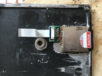
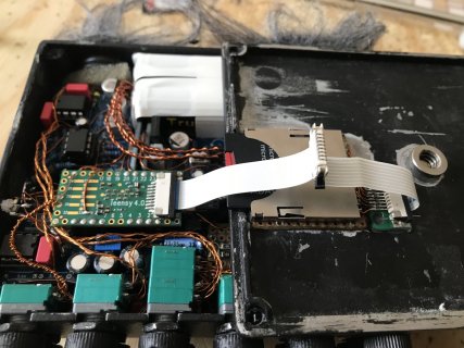
Here a couple of pics of the build. I tried also with a Sparkfun SD adapter like that some time ago, but same tickling noise. That's why I replaced it for this flex actually. This selfmade SD adapter goes on the chassis' lid and has 100ohm series resistors to all digital lines.
 

Attachments

  • IMG_5207.JPG
    IMG_5207.JPG
    351 KB · Views: 10
  • IMG_5210.JPG
    IMG_5210.JPG
    306.8 KB · Views: 9
Back
Top