You are using an out of date browser. It may not display this or other websites correctly.
You should upgrade or use an alternative browser.
You should upgrade or use an alternative browser.
Teensy 4.1 audio pin usage
- Thread starter bdoan
- Start date
MichaelMeissner
Senior Member+
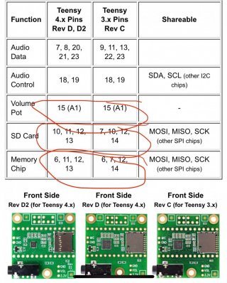
If you look at the schematic, you will see pin 15 has a 0.1uF capacitor and a 25K resistor on it. I believe these are to make analog inputs smoother.
Both pins 6 and 10 have 10K pull-up resistors that are typically used on SPI CS pins.
Pins 18 and 19 have 2.2K pull-up resistors that are needed for the I2C bus.
If you connect pins 6. 10, and 15, then these resistors and the capacitor may interfere any other uses of the pins.
Due to the fact that the revision D and D2 audio boards were made from the revision A-C audio boards, and just changed what pins are used, the 2 SPI devices (memory and SD) use the ground pin next to pin 0. While the volume control uses the ground pin between VIN and 3.3 volts. On the Teensy 4.0 and 4.1, these 2 pins are connected, but on the previous Teensy 3.0, 3.1, 3.2, 3.5, and 3.6 boards, the pin between VIN and 3.3 volt was the analog ground pin. I.e. you need to connect both pins to get the audio board to work completely.
It depends on what you are wanting to do with the pins. I would say the simplest approach is just not to connect pins 6, 10, and 15 between the Teensy and the Audio board, and then you should be able to use the pins in whatever fashion you want. If aren't using either the memory or the SD card, then you don't need to connect pins 11-13, but if you don't connect pins 6/10 and do connect 11-13, you should be able to use other SPI devices.
Obviously, pin 13 still has the LED on it, so that might affect things if you want to do a digital read from pin 13.


