Teensy Hook up Sainsmart 1.8" TFT

Status
Not open for further replies.
I am about to get my first Teensy 3.1 to use in my project, I need to connect the Sainsmart 1.8" TFT display, I was wondering how I would do this. The display uses SPI and I need to connect SCL, SDA, RS/DC, RES, and CS pins.
 
Not sure if it will work since there are slight deviations such as SCL and the page says SCLK (are they the same?), I assume res and rst are the same though, but SDA isn't present at all.
 
Names are a mixed bag SPI is a fixed thing - that page seems to be Teensy 3.0 era :: between the REF card and this display: https://www.pjrc.com/store/display_ili9341.html and maybe https://en.wikipedia.org/wiki/Serial_Peripheral_Interface_Bus and the code blocks maybe you can see the answer. [two more BINGS]

Code:
// This Teensy3 native optimized version requires specific pins
//
#define sclk 13  // SCLK can also use pin 14
#define mosi 11  // MOSI can also use pin 7
#define cs   10  // CS & DC can use pins 2, 6, 9, 10, 15, 20, 21, 22, 23
#define dc   9   //  but certain pairs must NOT be used: 2+10, 6+9, 20+23, 21+22
#define rst  8   // RST can use any pin
#define sdcs 4   // CS for SD card, can use any pin

#include <Adafruit_GFX.h>    // Core graphics library
#include <Adafruit_ST7735.h> // Hardware-specific library

Code:
// For optimized ILI9341_t3 library
#define TFT_DC      20
#define TFT_CS      21
#define TFT_RST    255  // 255 = unused, connect to 3.3V
#define TFT_MOSI     7
#define TFT_SCLK    14
#define TFT_MISO    12
 
EDIT#1: I really must 'preview' (/go advanced) before posting, can't claim I was ninja'd so much if timestamps on our posts are so far apart :embarrassed:

Code:
#define sclk 13  // SCLK can also use pin 14 [COLOR="#0000FF"]-- SCL[/COLOR]
#define mosi 11  // MOSI can also use pin 7 [COLOR="#0000FF"]-- SDA[/COLOR]
#define cs   10  // CS & DC can use pins 2, 6, 9, 10, 15, 20, 21, 22, 23
#define dc   9   //  but certain pairs must NOT be used: 2+10, 6+9, 20+23, 21+22
#define rst  8   // RST can use any pin [COLOR="#0000FF"]-- RES[/COLOR]
#define sdcs 4   // CS for SD card, can use any pin
mosi stands for "master out/slave in"

Edit#2: Soz defrag but BING is not anybody's friend, goog may be as evil as MS any day but inept and meaningless they manage not to be.
 
Last edited:
EDIT#1: I really must 'preview' (/go advanced) before posting, can't claim I was ninja'd so much if timestamps on our posts are so far apart :embarrassed:

Edit#2: Soz defrag but BING is not anybody's friend, goog may be as evil as MS any day but inept and meaningless they manage not to be.

ROB > Should'a used BING! Only apple is worse than Google - MSFT Rocks! :)

... confusion may come from this on sainsmart - I was looking or would have posted faster ;) . . . they call out SDA apart from MOSI ????

Signal Definition:
◾GND : Power Ground
◾VCC : 5V power input
◾CS : Chipselect for LCD,
◾SDA : LCD Data for SPI
◾SCL : SCLK for TFT Clock
◾RS/DC : Command/Data Selection
◾RESET : LCD controller reset, active low
◾CS (SD-CS) : Chipselect for TF Card,
◾CLK (SD-Clock): SPI Clock
◾MOSI (SD-DI) : SPI Master out Slave in
◾MISO (SD-DO) : SPI Master in Slave out
 
Thanks for the info, on a side note (kind of surprising) neither the wiki nor that other display talks about SDA.

*Wow that's totally weird how they are separately labeled! But thank you so much Rob and defragster for your help, now I don't need to buy a new display.
 
Last edited:
Indeed they don't [ninja credit to Rob] - I was trying to do a drive by and get off this computer . . . the Teensy 3.1 card doesn't show MOSI/MISO but DOUT/DIN and then for fun calls #18 SDA0. The LC card shows MOSI/MISO and doubles up on SDA's.

@ghostwubble: Post some details when you see it working with the T_3.1: on the pins and software, it might be good for the Wiki and help others.

The linked PJRC supported display is cheaper and may have better T_3.1 support - I got a couple and was impressed on the one I got in two days and fired up.
 
Last edited:
Looks like they are terming 'SDA' for the display interface and 'MISO/MOSI' for SD card interface.

(@defragster: Near its beginnings BING was simply useless - just checked and they have much more relevant (seeming) results for a couple of terms I tried but they used more bytes (with no perceivable benefit) to bring it to me and the format looks awful familiar...)
Edit: Oh yeah, $8 320x240 color display from PJRC - bloody fantastic, couldn't believe it was really a functional display for just $8 till I paid a little closer attention about the SD circuit on it; very glad I got one, can't wait to feel like there is enough in the bank to get a few more.
 
Last edited:
Hmmm, so to avoid confusion let me repeat what I understand so far
SCL-19
SDA-10
RS/DC-9
Rst-8
CS-10
Is this the correct wiring?
 
Looks like they are terming 'SDA' for the display interface and 'MISO/MOSI' for SD card interface.

(@defragster: Near its beginnings BING was simply useless - just checked and they have much more relevant (seeming) results for a couple of terms I tried but they used more bytes (with no perceivable benefit) to bring it to me and the format looks awful familiar...)

Yeah - that isn't made clear anywhere amongst the TLA barrage from a drive by glance.

BING is lame in many ways - MSFT can make a holographic IOT robot, but not a set of search Booleans and such? - but BING has the coolest pictures! I can make it work for me, since MSFT bought me my house. They also haven't grown a good phone ecosystem after 5 or 10 phone OS wipes.
 
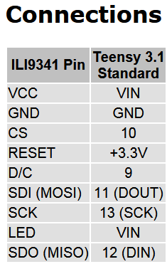
Wiring for T_3.1 should conform to this set of pins I'd think if the software allows: https://www.pjrc.com/store/display_ili9341.html

<EDIT> should be as specified in this table from the ILI9341 page above:
SPI_TFT.png
 
Last edited:
That wiring graphic for ILI9341 is very well defined for sure, if the SD circuit on the sainsmart display is usable and you want to use it then mentioning that it needs a unique CS signal from Teensy may be helpful - Edit: I mean that the rest of the (apparently) separate lines of the two sets SPI pins should be safe to tie; I have not looked at the DS nor schematic for the display so there may be something which makes this a bad idea but not likely imho.

@defragster: You quoted the information that made me say 'looks like they are terming....' - just mentioning to tease mostly but the clues are all in your post and I didn't look at any other pages than 'this one' to feel sure enough to post that.
 
Last edited:
Indeed - the PJRC ILI9341 page and product and code worked as shown for me enough to solder wires and have it work the first time. I saw post that showed the edits needed to use the SD portion (resistor removal/bypass) but I had unhooked mine and not gotten back to it yet. Here view of how fast the Teensy can push the ILI9341

@ghostwubble:From that thread this ILI9341 post/thread might provide some SPI background: Display_ili9341 { don't know if your SD interface is polluted with similar spare parts }. SPI is fast and somebody put 4 (5?) ILI9341's on the same T_3.1 as long as they had unique CS pins.
 
Well I am happy to say that the display worked using the teensy 3.1 using this pinout

vcc-vin
gnd-gnd
scl-13
sda-11
rs/dc-9
res-8
cs-10
 
Status
Not open for further replies.
Back
Top