-
-
 I'm building an effects device with Teensy4.0. I want to control Teensy4 FX parameters via I2C. A Teensy4.1 controls the FX parameters via I2C and supplies the audio signal to the Teensy4.0 via I2S. I have Teensy4.1 as the I2C master and...
 -
Just implemented a new tap_tempo function which can be called via MIDI clock callback, footswitch or something else. Here is a short sample of delay synced to a drum track with MIDI clock sent via USB: Another interesting feature is if just a...
-
Rolfdegen replied to the thread New Teensy 4.1 DIY Synthesizer.The Jeannie synthesizer kit is sold by exploding-shed. If you only need the circuit boards, you can get them from me. Link: https://www.exploding-shed.com/tubeohm-jeannie/100352 Jeannie Case here...
-
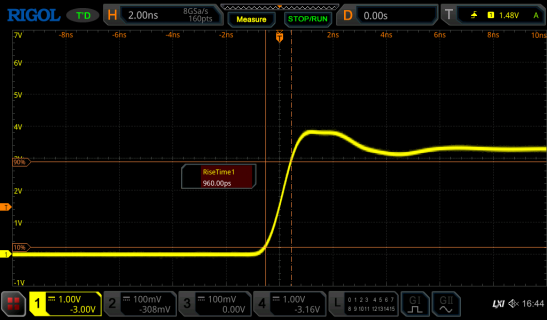
Rolfdegen replied to the thread High-speed digital I/O in teensy 4.1.My best RiseTime with Teensy4 and parallel GPIO Output is 960ps. Square frequency is 100KHz and CPU 600MHz. I have connected four GPIO outputs in parallel via 51R resistor. My code.. // 100KHz Square signal on Teensy4 with 4 Outs const int...
-
-
Rolfdegen replied to the thread High-speed digital I/O in teensy 4.1.Next step is an HF case from https://www.meilhaus.de/tbrfh.htm I want to install the circuit in the HF case. I hope it fits...
-
-
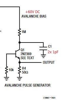
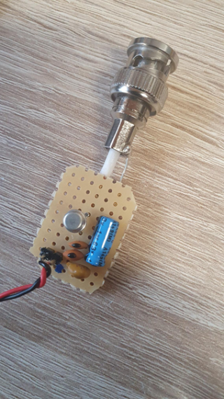
Rolfdegen replied to the thread High-speed digital I/O in teensy 4.1.I built a pulser based on Jim Williams' idea and tested it on my Rigol MSO5104 (350MHz hack)...
-
-
Rolfdegen replied to the thread Is there a CLKO pin on the Teensy4/4.1 ?.Paul. Danke für deine Informationen :)
-
The ATmega328 has no CLKO, it will accept an input clk into XTAL1 pin, limit 16MHz. There is no system clock output. You can generate 8MHz on some of the GPIO pins using suitably programmed PWM. 150MHz is a lot, more than is sensible for...
-
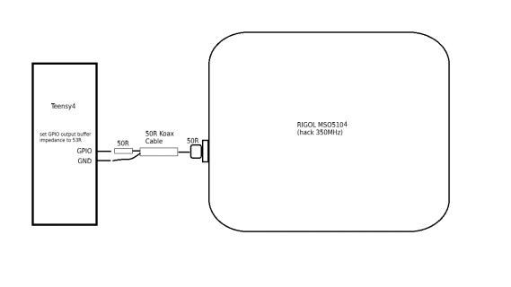
Rolfdegen replied to the thread High-speed digital I/O in teensy 4.1.My best result was with a 50 ohm series resistor and a 50 ohm coaxial cable. Oscilloscope input impedance of 50 ohms. Set GPPIO output impedance on Teensy4 // 50MHz Puls signal on Teensy4 const int my_pulse_pin = 22; void setup() {...
-
-
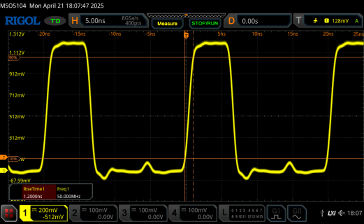
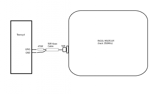
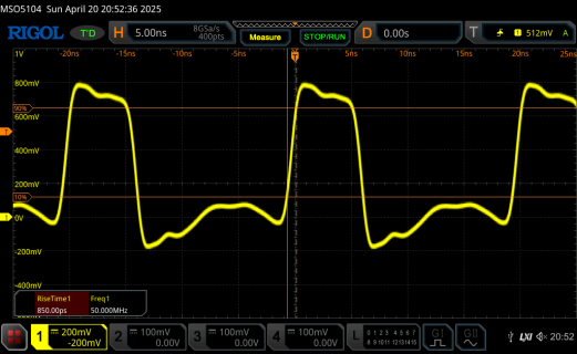
Rolfdegen replied to the thread High-speed digital I/O in teensy 4.1.50MHz pulse measurement with 450R series resistor, 50 Ohm coaxial cable and 50R Scope impedanz resistor.
-
-
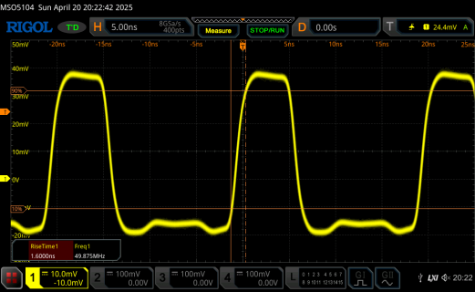
Rolfdegen replied to the thread High-speed digital I/O in teensy 4.1.50MHz pulse measurement with 10x Probe, series 450R resistor and 50R Scope impedanz resistor. I hope the measurement is correct :unsure:
-
-
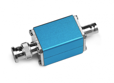
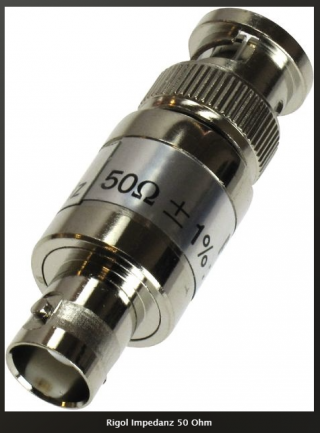
Rolfdegen replied to the thread High-speed digital I/O in teensy 4.1.50MHz pulse measurement with 1x probe and 50R Scope impedanz resistor Scope 50R Impedanz Adapter
-
-
Rolfdegen replied to the thread High-speed digital I/O in teensy 4.1.The maximum current load for the GPIO output on the Teensy4 is 4mA. A 50 Ohm terminating resistor would overload the output
-
-
For this sort of signal speed a low-impedance probe might be the best option, basically a 10:1 probe with 500 ohms input impedance and using 50 ohm setting at the scope. High impedance probes are capacitive-dividers at the top end of their...
-
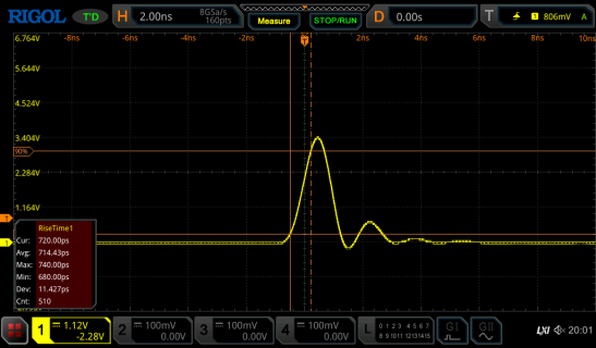
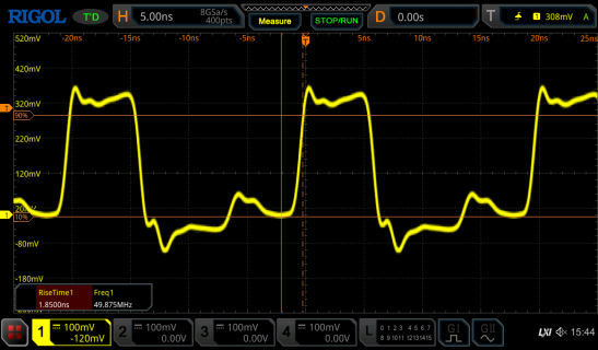
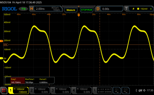
Rolfdegen replied to the thread High-speed digital I/O in teensy 4.1.Thanks Paul for your Tips. My 150 MHz signal with an Rigol MSO5104 (hacked to 350 MHz). I set the probe to x10 to make the measurement more precise. Code: const int my_pulse_pin = 20; void setup() { pinMode(my_pulse_pin, OUTPUT)...
-
-
Rolfdegen posted the thread Is there a CLKO pin on the Teensy4/4.1 ? in Technical Support & Questions.I need a simple signal with more than 150 MHz for measurements. The Atmega328 and Arduino nano have a pin labeled CLKO for this purpose.
-
Rolfdegen replied to the thread New polyhonic Teensy DIY Sampler.Another Fx project with Teensy4.0... https://github.com/mattvenn/teensy-audio-fx/tree/master
-
-
Rolfdegen replied to the thread New polyhonic Teensy DIY Sampler.Nice Jeannie project. I also had the idea of using the Teensy 4.0 for digital effects. But the question is, can you clone the beautiful effects from the FV-1 with the Teensy 4.0?
-
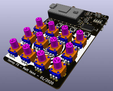
Rolfdegen replied to the thread New polyhonic Teensy DIY Sampler.My prototype schematic is finished. One or two things will definitely change. For example, the decision as to which effect module will be used in the Degenerator2 isn't quite clear yet. But the time will come, and the idea will come ;-) With that...
-
-
Rolfdegen reacted to Mudfork's post in the thread changing pitch of audio samples - TeensyVariablePlayback library with
 Like.
Just wanted to report back that the code works. Thanks! I removed the fade in Audacity, so I removed setLoopStart() and setLoopFinish() aswell. When I extend the crossfade, the loop is almost inaudible.
Like.
Just wanted to report back that the code works. Thanks! I removed the fade in Audacity, so I removed setLoopStart() and setLoopFinish() aswell. When I extend the crossfade, the loop is almost inaudible. -
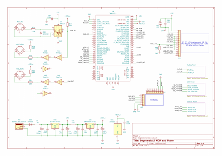
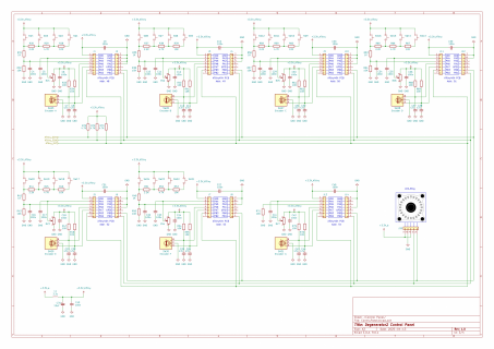
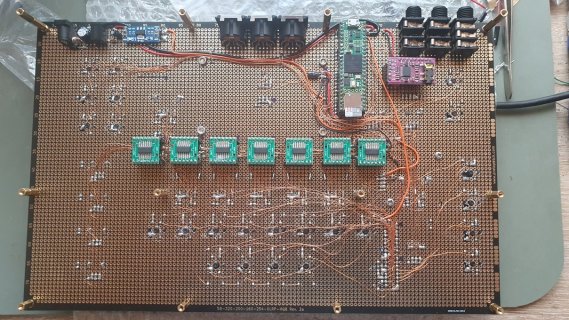
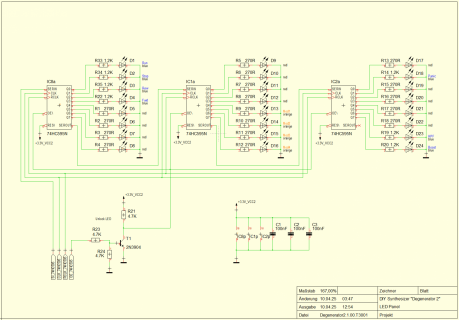
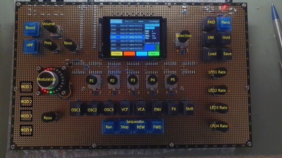
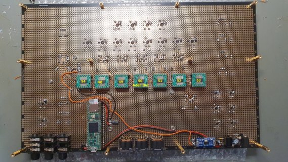
Rolfdegen replied to the thread New polyhonic Teensy DIY Sampler.Hello friends :) The first circuit diagrams from Degenerator2. Circuit diagrams for the MCU, power supply, MIDI, and display are coming soon. The control panel consists of seven ATiny404 modules. Each module has an analog input for four buttons...
-
-
Rolfdegen replied to the thread changing pitch of audio samples - TeensyVariablePlayback library.But..there is something wrong with your calculation for the sample rate :unsure: // map analog input 0-1023 to 0.5-3.0 pitch double getPlaybackRate(int16_t analog) { //analog: 0..1023 return ((analog / 1023) * 2.5) + 0.5; This is my...
-
Rolfdegen replied to the thread changing pitch of audio samples - TeensyVariablePlayback library.The test was successful. Teensy plays the sample :) This my code.. #include <Arduino.h> #include <Audio.h> #include <SD.h> #include <TeensyVariablePlayback.h> // GUItool: begin automatically generated code AudioPlaySdResmp playSdWav1...
-
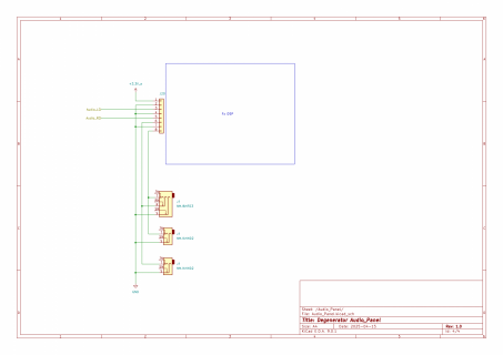
Rolfdegen replied to the thread changing pitch of audio samples - TeensyVariablePlayback library.Okay. I'll check it for you. I have a Teensy4.0 and an SGTL5000 DAC board.
-
Rolfdegen replied to the thread changing pitch of audio samples - TeensyVariablePlayback library.Check your libs for play samples.. thas me.. newdigate/TeensyAudioFlashLoader@^1.0.8 newdigate/TeensyVariablePlayback@^1.1.0 Do you hear a sound ?
-
Rolfdegen replied to the thread changing pitch of audio samples - TeensyVariablePlayback library.Which Teensy type do you use and how long your wave file ?
-
Rolfdegen replied to the thread changing pitch of audio samples - TeensyVariablePlayback library.You still need to set the loop_type :unsure: In the loop_type.h define this.. typedef enum loop_type { looptype_none, // 0 looptype_repeat, // 1 looptype_pingpong // 2 } loop_type; play sample.. float rate =...
-
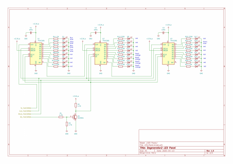
Rolfdegen replied to the thread Teensy 4.1 Problem setting output pin before its declaration.My Led panel.. My Teensy code.. // LED driver // Pin connected to ST_CP of 74HC595 int latchPin = 30; // Pin connected to SH_CP of 74HC595 int clockPin = 31; // Pin connected to DS of 74HC595 int dataPin = 32; // Pin connected to OE of 74HC595...
-
-
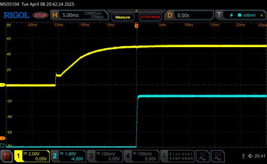
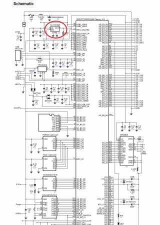
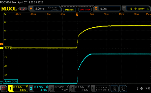
Rolfdegen replied to the thread Teensy 4.1 Problem setting output pin before its declaration.Ok. I think it's the problem comes from the +3.3V supply voltage from Teensy Board. The Teensy gets its +5V supply voltage on pin Vin (yellow curve). After 15ms, the TLV75733P chip on the Teensy switches on the +3.3V supply voltage on the 3.3V...
-
-
Rolfdegen replied to the thread Teensy 4.1 Problem setting output pin before its declaration.I tried that, but it didn't help. The only thing that helps is the transistor inverter circuit.
-
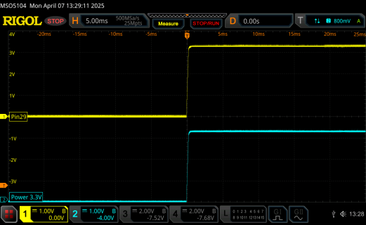
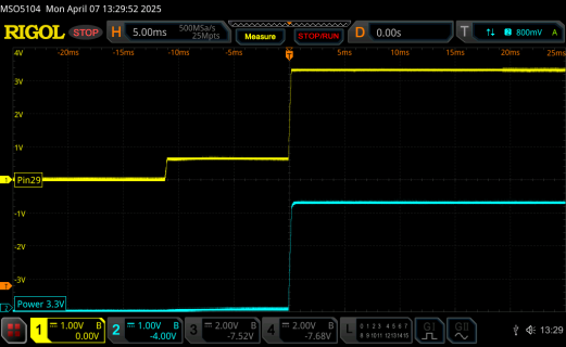
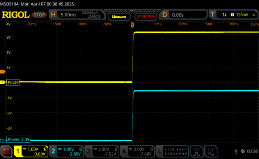
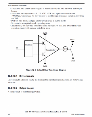
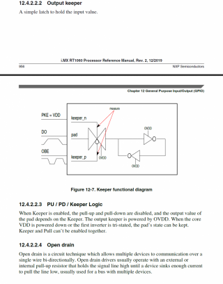
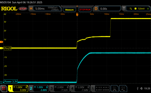
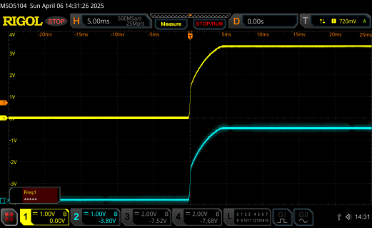
Rolfdegen replied to the thread Teensy 4.1 Problem setting output pin before its declaration.It's clearly due to my power supply in the DIY project. 1st image shows a 4.7K pull-up on Teensy4.1 pin 29 with +5V and +3.3V from the Teensy. 2nd image shows a 4.7K pull-up on Teensy4.1 pin 29 with +5V and +3.3V from the DIY project's power...
-
-
Rolfdegen replied to the thread Teensy 4.1 Problem setting output pin before its declaration.As I suspected, it's the power supply. My test power supply delivers a stable 5V supply voltage immediately after switching off from standby. The voltage regulator on my DIY board takes a few milliseconds to adjust the voltage from +12V to +5V...
-
Rolfdegen replied to the thread Teensy 4.1 Problem setting output pin before its declaration.Mmmm :unsure: I've now used a Teensy4.0 board and am getting different results. Since the Teensy4.0 doesn't have pin 29, I used a different pin 2 with an external 4.7K pull-up connected to +3.3V from the Teensy. The signal is almost identical...
-
-
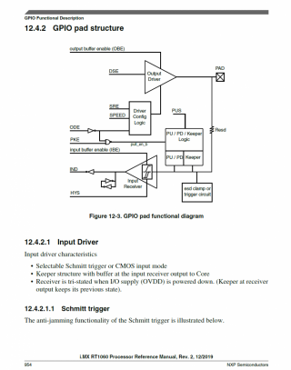
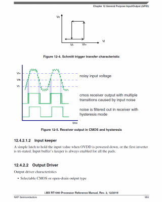
Rolfdegen replied to the thread Teensy 4.1 Problem setting output pin before its declaration.Maybe it is also due to the complex GPIO structure with ESD clamp circuit in the Teensy MCU :unsure:
-
-
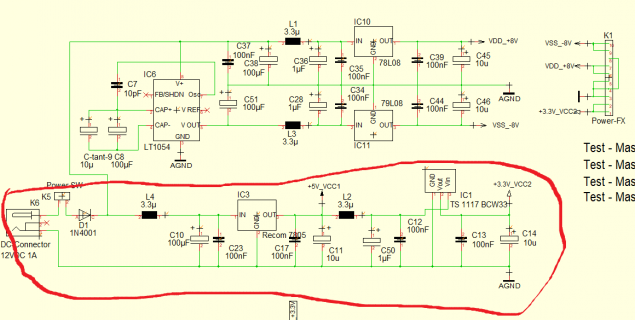
Rolfdegen replied to the thread Teensy 4.1 Problem setting output pin before its declaration.I can't explain it either. The pull-up resistor is connected to a separate 3.3 volt line. Perhaps that's the cause. I supply the entire circuit with +12V. The Teensy is supplied with +5V via a switching regulator. I generate the +3.3V using a...
-
-
Rolfdegen replied to the thread Teensy 4.1 Problem setting output pin before its declaration.Init the light shown on my Synth project.. There are 24 status LEDs in different colors for the 24 keys. These are controlled by three 74HC595 slide switches. For some keys, the LEDs are not yet wired.
-
Rolfdegen replied to the thread Teensy 4.1 Problem setting output pin before its declaration.pinMode(29, INPUT_PULLUP); pinMode(29, OUTPUT); digitalWriteFast(29, HIGH); 4.7K and I also tried different pins on the Teensy and always tested in connection to the gate input of the 74HC595. Measured here with 4.7K pullup on the Teensy pin...
-
-
Rolfdegen replied to the thread Teensy 4.1 Problem setting output pin before its declaration.4.7K and I also tried different pins on the Teensy4.1
-
Rolfdegen replied to the thread Teensy 4.1 Problem setting output pin before its declaration.But there's still time left for the Teensy MCU's reset phase. A few milliseconds, I estimate. The outputs aren't defined :unsure:
-
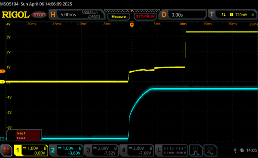
Rolfdegen replied to the thread Teensy 4.1 Problem setting output pin before its declaration.Scope signals with my Gate circuit.. The gate pin on the 74HC595 is faster high and 74HC595 outputs off. When switched power on, all LEDs are off :)
-
-
Rolfdegen replied to the thread Teensy 4.1 Problem setting output pin before its declaration.pinMode(29, INPUT_PULLUP); pinMode(29, OUTPUT); digitalWriteFast(29, HIGH); The oscilloscope shows the voltage rise of the supply voltage (blue) and pin 29 (Gate 74hc595) on the Teensy4.1 (yellow) during power-up. The gate pin on the 74HC595...
-
-
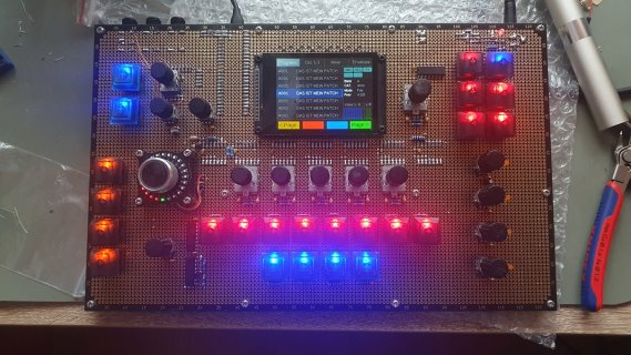
Rolfdegen replied to the thread New polyhonic Teensy DIY Sampler.Small light show with Degenerator 2
-
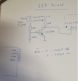
Rolfdegen replied to the thread Teensy 4.1 Problem setting output pin before its declaration.Hallo Teensys.. I had a similar problem. I'm using three 74HC595s on the Teensy4.1. During power-up, the 74HC595 outputs had random values, and some LEDs were lit. Solution: I connected the gate pin of the 74HC595 to a Teensy control line using a...
-
-
Rolfdegen reacted to positionhigh's post in the thread A DX7 (Fm synthesis) replacement with Dexed on a Teensy with Like.
-
Rolfdegen replied to the thread New polyhonic Teensy DIY Sampler.Degenerator.2 in action..
-
Rolfdegen replied to the thread New polyhonic Teensy DIY Sampler.All buttons are illuminated! Below the mod control is the fixed control for filter resonance. With the buttons Mod 1-4 a different modulator source can be selected and controlled with the Modulation controller.
-
Rolfdegen replied to the thread New polyhonic Teensy DIY Sampler.All buttons are illuminated! Below the mod control is the fixed control for filter resonance. Back
-
-
Rolfdegen replied to the thread New polyhonic Teensy DIY Sampler.A sign of life... I think I'll choose a dark blue as the background color for all the LEDs on the LED ring, and change to orange when I turn up the volume.
-
-
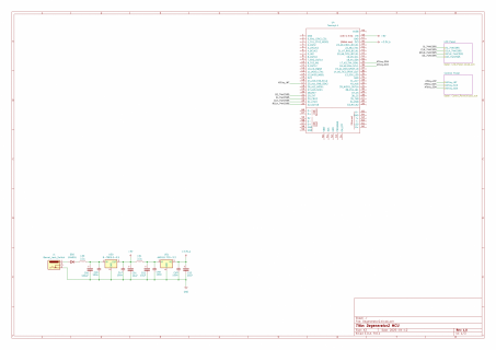
#include <Audio.h> AudioInputUSB usb1; AudioOutputI2SOct i2s_oct1; AudioAmplifier amp1; AudioAmplifier amp2; AudioAmplifier amp3; AudioAmplifier amp4; AudioAmplifier amp5; AudioAmplifier amp6; AudioAmplifier amp7; AudioAmplifier...
-
-
-
Loading…
-
Loading…