CrustyAuklet
Member
I am working on a project to collect scientific data from sensors via the ADC, at high sample rates (right now at about 150-160ksps). The data is not being stored on the Teensy, but is being piped into a linux computer for a variety of processing and machine learning tasks. The Teensy is basically a buffer right now though we might do a few more things in the future.
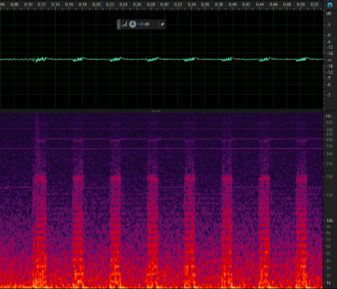
Everything seems to be working well but transmitting the data over USB seems to be producing noise in the readings. The sensors are still under development so right now I am using an adafruit microphone to test. Sample buffers are sent over USB once they are full and the rate at which they get sent matched perfectly with the frequency of the noise I see in the data (when I adjust sample rate or buffer size).
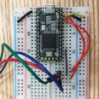
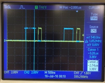
Circuit & Noise:


I am using platformIO with makefiles (Clion), and the arduino framework. Only using the ADC library right now. Code attached. Any advice or help would be great
Everything seems to be working well but transmitting the data over USB seems to be producing noise in the readings. The sensors are still under development so right now I am using an adafruit microphone to test. Sample buffers are sent over USB once they are full and the rate at which they get sent matched perfectly with the frequency of the noise I see in the data (when I adjust sample rate or buffer size).
Circuit & Noise:


I am using platformIO with makefiles (Clion), and the arduino framework. Only using the ADC library right now. Code attached. Any advice or help would be great
Code:
/**
 * TeensyADC - High speed audio sampling with the teeny 3.2 ARM board This code samples the ADC on the teensy3.2 at
 *   the highest stable rate possible and dumps that data out the USB port using a double buffer. The purpose of
 *   this is for high speed bio-acustics, where most of the processing will be done on a second board
 *   (intel edison at the moment)
 *
 *   Enable the debug and hook pin 2 and 3 to an oscilloscope to watch the timing. Further optimizations
 *   Could be possible to increase speed. As well as analog signal processing on
 *   the input before sampling.
 *
 * @author Ethan Slattery
 * @contact Ethan.Slattery@yahoo.com
 * @date 15-July-2016
 */
#include <ADC.h>

#define BIT_DEPTH 12            // 13-bit usable ADC sample, Mask with 0x1FFF (8, 10, 12 or 16)
#define SAMPLE_AVERAGES 1       // Increases sample time linearly (0, 4, 8, 16 or 32)
#define SAMPLE_RATE_HZ 150000    // Highest stable sample rate at the moment is 160000, which leaves a 2.6us gap for USB wich takes 2.5us
#define BUFFER_SIZE 8192        // Size of the buffer in samples (should be multiple of 512, 64k of ram avail)

#define DEBUG_ON 0              // enables the debug GPIO (disable for depoyment)
#define DEBUG_PIN_1 2           // GPIO pin for timing the read ISR
#define DEBUG_PIN_2 3           // GPIO pin for timing the PDB frequency
#define LED_PIN LED_BUILTIN     // Teensy 3.2 Built in LED pin
#define READ_PIN A2             // Pin for sampling the audio input

//elapsedMicros benchmark1;       // Benchmark timer, auto increasing obj :)
ADC *adc = new ADC();             // The ADC object

/*** GLOBAL DATA VARIABLES ***/
uint16_t  buff0[BUFFER_SIZE];  // Buffer for the samples to send over USB
uint16_t  buff1[BUFFER_SIZE];  // Buffer for the samples to send over USB
uint8_t   header[]  = {0xFF, 0xFF}; // Header bytes for delimiting packets
const int HEADER_SIZE = 2;          // Size of the header buffer

/*** GLOBAL LOGIC VARIABLES ***/
volatile int  buffCounter   = 0;    // Keeps track of the samples in buffer
volatile int  currentBuffer = 0;    // Tracks the currently active buffer
volatile bool buff0Ready = false;   // Flag to set buffer 0 ready for sending
volatile bool buff1Ready = false;   // Flag to set buffer 1 ready for sending

void setup(void) {
    // Set all the pin modes
    pinMode(LED_PIN, OUTPUT);      // LED PIN
    pinMode(DEBUG_PIN_1, OUTPUT);  // hardware debug pin
    pinMode(DEBUG_PIN_2, OUTPUT);  // hardware debug pin
    pinMode(READ_PIN, INPUT);      // ADC sampling for hydrophone

    // Start serial output, 12Mbit/sec no matter what over teensy USB
    Serial.begin(115200);

    /*** Setup the ADC samples ***/
    adc->setAveraging(SAMPLE_AVERAGES);
    adc->setResolution(BIT_DEPTH);
    adc->setReference(ADC_REF_3V3);

    // Set the conversion and sampling speed of the single ADC measurements
    // Options: ADC_VERY_LOW_SPEED, ADC_LOW_SPEED, ADC_MED_SPEED,
    //          ADC_HIGH_SPEED_16BITS, ADC_HIGH_SPEED or ADC_VERY_HIGH_SPEED
    adc->setConversionSpeed(ADC_HIGH_SPEED);
    adc->setSamplingSpeed(ADC_HIGH_SPEED);

    // Enable intterrupts on the ADC module (ADC_0 or ADC_1)
    adc->enableInterrupts(ADC_0);

    // Perform one read to burn in settings
    adc->analogRead(READ_PIN, ADC_0);

    // Start the PDB timer at the given freq.
    adc->adc0->stopPDB();
    adc->adc0->startPDB(SAMPLE_RATE_HZ);

    // slight delay to let everything settle and flash light to show setup is complete
    digitalWrite(LED_BUILTIN, HIGH);
    delay(500);
    digitalWrite(LED_BUILTIN, LOW);
    delay(250);

    while(!Serial){}

    // blink LED to show serial is connected and sampling starts
    digitalWrite(LED_BUILTIN, HIGH);
    delay(250);
    digitalWrite(LED_BUILTIN, LOW);

} // END of setup()

void loop(void) {

    // If buff0 is ready to send, send it and toggle the ready flag
    if(buff0Ready) {
#if DEBUG_ON
            digitalWriteFast(DEBUG_PIN_1, HIGH);
            digitalWriteFast(LED_PIN, HIGH);
#endif
            Serial.write(header, HEADER_SIZE);
            Serial.write(reinterpret_cast<char *>(buff0), BUFFER_SIZE * 2);
#if DEBUG_ON
            digitalWriteFast(DEBUG_PIN_1, LOW);
#endif
        buff0Ready = false;
    }

    // If buff1 is ready to send, send it and toggle the ready flag
    if(buff1Ready) {
        // Only write to serial if the port is open
#if DEBUG_ON
            digitalWriteFast(DEBUG_PIN_1, HIGH);
#endif
            Serial.write(header, HEADER_SIZE);
            Serial.write(reinterpret_cast<char *>(buff1), BUFFER_SIZE * 2);
#if DEBUG_ON
            digitalWriteFast(DEBUG_PIN_1, LOW);
            digitalWriteFast(LED_PIN, LOW);
#endif
        buff1Ready = false;
    }

    // If the ADC fail flag is set, output the error
    if(adc->adc0->fail_flag) {
#if DEBUG_ON
        Serial.print("ADC0 error flags: 0x");
        Serial.println(adc->adc0->fail_flag, HEX);
#endif
        if(adc->adc0->fail_flag == ADC_ERROR_COMPARISON) {
            adc->adc0->fail_flag &= ~ADC_ERROR_COMPARISON; // clear that error
#if DEBUG_ON
            Serial.println("Comparison error in ADC0");
#endif
        }
    } // End of error message handler

} // END OF LOOP()

/**
 * ADC Interrupt Service Routine
 * This ISR is called once the ADC (triggered by the PDB) is done with it's
 * measurement. The appropriate buffer is then selected and the sample is placed
 * into the appropriate buffer, split into two bytes if necessary. This entire
 * ISR currrently takes 1.2usec to execute.
 */
void adc0_isr() {
    #if DEBUG_ON
    digitalWriteFast(DEBUG_PIN_1, HIGH);
    #endif

    // Switch buffer if necessary
    if(buffCounter == BUFFER_SIZE && currentBuffer == 0) {
        buffCounter = 0;
        currentBuffer = 1;
        buff0Ready = true;
    }
    else if(buffCounter == BUFFER_SIZE && currentBuffer == 1) {
        buffCounter = 0;
        currentBuffer = 0;
        buff1Ready = true;
    }

    // Write to the propper buffer (8-bit Readings!)
    if (currentBuffer == 0) { buff0[buffCounter++] = uint16_t(adc->readSingle()); }
    if (currentBuffer == 1) { buff1[buffCounter++] = uint16_t(adc->readSingle()); }

    #if DEBUG_ON
    digitalWriteFast(DEBUG_PIN_1, LOW);
    #endif
}

/**
 * PDB interrupt
 * This interrupt is called when the PDB starts an ADC sample. The starting of
 * a sample is automatic, so the only code needed here is to clear the PDB flag.
 * Once the sample is done the ADC will trigger an interrupt, currently each
 * Sample is ready in 1.72usec
 */
void pdb_isr(void) {
    #if DEBUG_ON
    digitalWriteFast(DEBUG_PIN_2, HIGH);
    #endif

    // Clears the interrupt flag from the PDB
    PDB0_SC &=~PDB_SC_PDBIF;

    #if DEBUG_ON
    digitalWriteFast(DEBUG_PIN_2, LOW);
    #endif
}
Attachments
Last edited:


