Faster way to read a single byte from Flash (or ext PSRAM)?

Hello all-
I have a Teensy 4.1 project that would greatly benefit by being able to read a single byte of a >1MB array in the order of 200nS. Unfortunately, I can't squeeze enough space out of RAM, so I'm looking to read directly from the on-board flash (preferred since there's plenty) or external PSRAM or flash if needed. I also need full random access, so caching doesn't help in this case.

Currently, using the following code, I can read a (cache miss) byte in about 400nS from on-board flash and >500nS for PSRAM. I haven't bothered playing with the ext clk freq since it would have to be twice as fast or more.
Code:
   volatile uint8_t dummy;   
   //volatile uint8_t* RAM_Image = (uint8_t*)0x60000000;  //on-board Flash
   volatile uint8_t* RAM_Image = (uint8_t*)0x70000000;  //ext PSRAM

   StartCycCnt = ARM_DWT_CYCCNT;
   dummy = RAM_Image[Cnt];
   StartCycCnt = ARM_DWT_CYCCNT - StartCycCnt;

If I change the code to provide a scope trigger:
Code:
   digitalWriteFast(TriggerPin, HIGH);
   dummy = RAM_Image[Cnt];
   digitalWriteFast(TriggerPin, LOW);

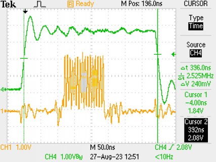
I see the following on the trigger and clock (ext PSRAM in this case)
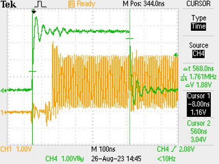
TEK0001.JPG

Zooming in, I count about 40 clocks before the function returns the byte I need. However, I believe QSPI should only need about 14 clocks (2 inst, 6 addr, 4 turn-around, 2 payload) for a single byte, so it appears to be loading at least the full 32 bit value, or more, before returning.

So, my question is, is there a way to instruct it to read a single byte and return quickly? Or other method to more quickly fetch a single byte?
I thought about going to the manual SPI method for external, but not sure about the overhead or ability for the local flash. Would prefer to use the integrated capabilities, but I'll take whatever ideas you may have. :)

Thank you much!
 
Last edited:
Guessing you're trying to emulate a parallel ROM?
You can bypass the cache/AHB bus by accessing the FlexSPI IP registers directly. For example: https://forum.pjrc.com/threads/6245...Access-Latency?p=249482&viewfull=1#post249482
But even if you raise the PSRAM clock speed (also mentioned in that thread) it won't be guaranteed under 200ns per random read.

You got it, somehow I missed that in my searching. Thanks!
Unfortunately, yes, I have a similar application and am coming to the same conclusion. :(

Even using the FlexSPI registers direct and clocking at 132MHz, I get this:
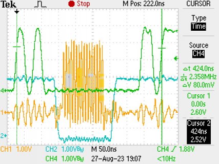
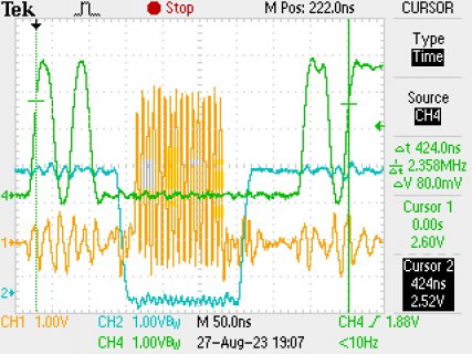
TEK0003.JPG

I count 16 PSRAM clocks, which is close to my assumption of 14 for a byte
Still nearly 400nS, which correlates with the CPU clock counts in the other post.
Looks like a good 100nS of waiting around after the transaction though, not sure why FLEXSPI_INTR_IPRXWA doesn't come back a little sooner, also takes some time on the front end.
The transaction itself is <150nS, but the pre/post nearly triples that...
 
Check out the FlexSPI FLSHA1CR1 register setting. It's documented in the reference manual on pages 1687-1689.

I believe we're configuring a pretty conservative (slow) setup and hold time... basically left over from the earliest QSPI experiments. Maybe it's time to really look at what these settings should be? Please keep in mind the default needs to work with 2 PSRAM or 1 PSRAM and 1 Flash chip.

This is the code in startup.c.

Code:
        FLEXSPI2_INTEN = 0;
        FLEXSPI2_FLSHA1CR0 = 0x2000; // 8 MByte
        FLEXSPI2_FLSHA1CR1 = FLEXSPI_FLSHCR1_CSINTERVAL(2)
                | [COLOR="#FF0000"]FLEXSPI_FLSHCR1_TCSH(3)[/COLOR] | [COLOR="#FF0000"]FLEXSPI_FLSHCR1_TCSS(3)[/COLOR];
        FLEXSPI2_FLSHA1CR2 = FLEXSPI_FLSHCR2_AWRSEQID(6) | FLEXSPI_FLSHCR2_AWRSEQNUM(0)
                | FLEXSPI_FLSHCR2_ARDSEQID(5) | FLEXSPI_FLSHCR2_ARDSEQNUM(0);

Really hoping you might try different settings and share scope screenshots.
 
CSINTERVAL might also play a part, especially if you're running the test code in a loop (although it's unclear if the hardware enforces it for every read or only consecutive reads/when necessary).
This is one of many cases where the documentation contradicts itself; supposedly CSINTERVALUNIT specifies whether CSINTERVAL is in single ticks or multiples of 256, but on page 1644 it is declared to be a multiple of 1024 ticks.
 
Thanks for the ideas, and the location in the datasheet! :)
Unfortunately it didn't help with my issue, but there were some interesting results...

All testing was done with 132MHz SCLK and CPU speed of 816MHz. (code pasted below)
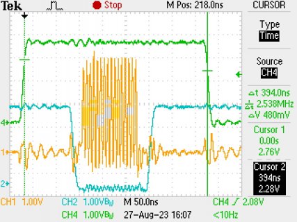
My initial shots didn't include CS, so I added it to these captures along with SCK and the trigger signal.

First, the default case (same as prev msg)
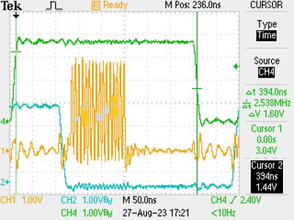
CSINTERVAL=2, TCSH=3, TCSS=3
TEK0004.JPG

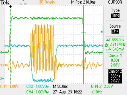
Then, deceased setup/hold to 0:
CSINTERVAL=2, TCSH=0, TCSS=0
TEK0005.JPG
Slightly (~26nS) faster. Makes sense since the units for setup/hold are number of serial clocks.

Increased setup/hold to 10:
CSINTERVAL=2, TCSH=10, TCSS=10
TEK0008.JPG
Slowed down and more front/back porch for CS shown.

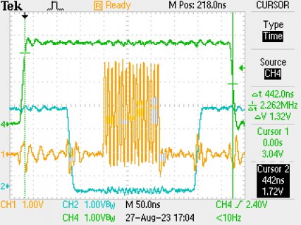
Here's the interesting part: when I increase the setup time, the overall time increases with it, as I'd expect. But when I increase the hold time, it pushed out CS, but doesn't impact the overall time at all. It even returns with CS still low.
CSINTERVAL=2, TCSH=31, TCSS=3
TEK0013.JPG

Next, I set setup/hold back to 3 (defaults) and played with the other CS settings. None of these had any effect on the waveforms at all, must only impact sequential reads.
CSINTERVAL = 10
CSINTERVAL = 100
CSINTERVALUNIT = 1 (default is 0), CSINTERVAL = 2
CSINTERVALUNIT = 1, CSINTERVAL = 100
Finally, decided to set these two as well, but same results from a single read.
AWRWAITUNIT = 2, AWRWAIT = 100 (default is 0 for both)

So, seems like these settings are fine. I guess the extra time spent is just overhead from the FlexSPI engine? Of course, if I remove the read setup/execution code, the pulse is about 4nS wide from SW and on the scope.
Happy to try other experiments if you have other ideas, but guessing it is what it is...

Here's the code used:
Code:
#define CycTonS(N)  (N*(1000000000UL>>16)/(F_CPU_ACTUAL>>16))
#define TriggerPin  33

extern "C" uint32_t set_arm_clock(uint32_t frequency);

FASTRUN void setup()
{
   set_arm_clock(816000000); //overclock CPU
   
   //set sclk to 132 Mhz:
   CCM_CCGR7 |= CCM_CCGR7_FLEXSPI2(CCM_CCGR_OFF);
   CCM_CBCMR = (CCM_CBCMR & ~(CCM_CBCMR_FLEXSPI2_PODF_MASK | CCM_CBCMR_FLEXSPI2_CLK_SEL_MASK))
     | CCM_CBCMR_FLEXSPI2_PODF(4) | CCM_CBCMR_FLEXSPI2_CLK_SEL(2); // 528/5 = 132 MHz
   CCM_CCGR7 |= CCM_CCGR7_FLEXSPI2(CCM_CCGR_ON);
   
   //FlexSPI setup:
   FLEXSPI2_INTEN = 0;
   FLEXSPI2_FLSHA1CR0 = 0x2000; // 8 MByte    
   FLEXSPI2_FLSHA1CR1 = FLEXSPI_FLSHCR1_CSINTERVAL(2)
           | FLEXSPI_FLSHCR1_TCSH(3) | FLEXSPI_FLSHCR1_TCSS(3);
   FLEXSPI2_FLSHA1CR2 = FLEXSPI_FLSHCR2_AWRSEQID(6) | FLEXSPI_FLSHCR2_AWRSEQNUM(0)
           | FLEXSPI_FLSHCR2_ARDSEQID(5) | FLEXSPI_FLSHCR2_ARDSEQNUM(0);
           
   pinMode(TriggerPin, OUTPUT);
   digitalWriteFast(TriggerPin, LOW);
   
   Serial.begin(115200);
   while (!Serial);
   Serial.printf("\n---Started-------------------\n");

   uint32_t StartCycCnt;
   volatile uint8_t dummy;
   //arm_dcache_flush_delete((void *)0x70000000, 1);  

   cli();
   StartCycCnt = ARM_DWT_CYCCNT;
   digitalWriteFast(TriggerPin, HIGH);

   FLEXSPI2_IPCR0 = 0; //address in flash
   FLEXSPI2_IPCR1 = FLEXSPI_IPCR1_ISEQID(5);
   FLEXSPI2_IPCMD = FLEXSPI_IPCMD_TRG;
   while (!(FLEXSPI2_INTR & FLEXSPI_INTR_IPRXWA)) ;
   dummy = FLEXSPI2_RFDR0;
   FLEXSPI2_INTR = FLEXSPI_INTR_IPCMDDONE | FLEXSPI_INTR_IPRXWA;
   
   StartCycCnt = ARM_DWT_CYCCNT - StartCycCnt;
   digitalWriteFast(TriggerPin, LOW);
   sei();

   Serial.printf("CPU: %dMHz  Cyc: %d  Time: %dnS\n\n", (F_CPU_ACTUAL/1000000), StartCycCnt, CycTonS(StartCycCnt));
}

void loop() 
{ }
 
Last edited:
Had to try one more thing, toggling the trigger signal between setup/readback commands:
Code:
   digitalWriteFast(TriggerPin, HIGH);
   FLEXSPI2_IPCR0 = 0; //address in flash
   digitalWriteFast(TriggerPin, LOW);
   FLEXSPI2_IPCR1 = FLEXSPI_IPCR1_ISEQID(5);
   digitalWriteFast(TriggerPin, HIGH);
   FLEXSPI2_IPCMD = FLEXSPI_IPCMD_TRG;
   digitalWriteFast(TriggerPin, LOW);
   while (!(FLEXSPI2_INTR & FLEXSPI_INTR_IPRXWA)) ;
   digitalWriteFast(TriggerPin, HIGH);
   dummy = FLEXSPI2_RFDR0;
   digitalWriteFast(TriggerPin, LOW);
   FLEXSPI2_INTR = FLEXSPI_INTR_IPCMDDONE | FLEXSPI_INTR_IPRXWA;
   digitalWriteFast(TriggerPin, HIGH);

Yields this:
TEK0015.JPG

Not unusual that the dummy readback takes a little longer than the others since it's a read and write.
However, there's still about 70nS from CS going high to FLEXSPI_INTR_IPRXWA indicating finished, or 100nS from the last data being clocked in.
 

Attachments

  • TEK0014.JPG
    TEK0014.JPG
    142.5 KB · Views: 57
Last edited:
Back
Top