mjs513's latest activity
-
 Meanwhiles, for anyones enjoyment, here is a video of a music player demo running on LVGL v9.0.0 I think there is a lot of room left to optimize. It has two screen sized frame buffers (1.3Mb each) that LVGL writes into, and the eLCDIF reads from...
 -
I made quick note somewhere on past pages with initial speed results showing longer at faster - but not seen with current test. Another thing the 'OneScanCap.ino' occasionally shows is an added 3 seconds to all times across the tests between one...
-
mjs513 replied to the thread Call to arms | Teensy + SDRAM = true.Sorry been distracted today for a bunch of reasons. Reran the tests but added the time to copy the array DMAMEM to EXTMEM: 0 errors, 1010 microseconds to copy DMAMEM to DMAMEM: 0 errors, 319 microseconds to copy RAMMEM to RAMMEM: 0 errors...
-
I will try to get back to trying it on this board. Sort of a PIA at times to hook up all of the wires in a secure enough way. So I much easier playing using the other boards. Did find using my camera shifter boards I did during the T4.1...
-
mjs513 replied to the thread Call to arms | Teensy + SDRAM = true.yep DMAMEM uint16_t array1[(320) * 240] __attribute__((aligned(32))); EXTMEM uint16_t array2[(320) * 240] __attribute__((aligned(32))); int errorCnt = 0; int arraySize = (320 * 240); void setup() { Serial.begin(115200); while (!Serial &&...
-
mjs513 reacted to PaulStoffregen's post in the thread EHEX has EOF twice in the file - Confuses FlasherX with
 Like.
Confirm, I generally don't comment on this code security stuff beyond the info already published on the code security web page and in the core library code, the 3 automatically generated programs and Arduino IDE plugin code. The NDA and...
Like.
Confirm, I generally don't comment on this code security stuff beyond the info already published on the code security web page and in the core library code, the 3 automatically generated programs and Arduino IDE plugin code. The NDA and... -
🤔I have not seen the problem of using the 8MBtye SDRam on the GIGA for the camera to read into. But when I looked at their schematic their SDRam setup looks very different than what I believe you are doing on these dev boards. That is they...
-
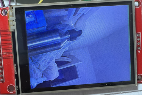
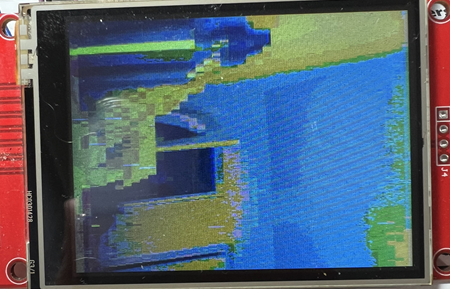
mjs513 replied to the thread Call to arms | Teensy + SDRAM = true.Just by way of an update @KurtE got the OV7670 and OV7670 video working using the micromod as the test platform. If you try it on the SDRAM something strange is going on. If you use DMAMEM for the framebuffers image is perfect if you use...
-
-
Those values use SEMC clock ticks as units, they don't care about the CPU's clock.
-
I set it to 1 and skipped 133 as I figured there was no point in testing it - we know it works
-
Nice, as expected no cap seems to work up to 206 MHz - based on prior runs by one or more others, and here. Odd though it should have a line for 133 MHz if the downloaded sketch LINE#1 wasn't changed from: #define FIRST_SPEED 0 And looking at...
-
@defragster Test with no cap Test results 57 tests with 5 ReReads: At 166 MHz in 142 seconds with 0 read errors At 196 MHz in 132 seconds with 0 read errors At 206 MHz in 130 seconds with 0 read errors At 216 MHz in 128...
-
Posted this just now: https://github.com/mjs513/SDRAM_t4/tree/main/examples/OneScanCap and running with DevBoard v 4.0 and twin 6.8 pF caps the summary is: Test results 57 tests with 5 ReReads: At 133 MHz in 157 seconds with 0 read errors...
-
Ugh… I should have multiplied the screen resolution by sizeof(uint32_t) in the flush call.. 🤦🏻♂️ How did I miss that one? Will test in a couple of hours - I'm sure that’s going to fix it. But regardless, the L1 Cache application notes does...
-
It's relatively simple to walk through all the MPU regions and add a new one at the end. Shouldn't need to disable/enable the data cache as long as it's done before the SDRAM/SEMC initialization. I agree that it should not be necessary though as...
-
If Paul suggests that, it would be worth a try to emulate the needed parts of that config function to add that new non-cache region. As I read the startup.c code for the configure_cache() it seemed like altering the cache/MPU when already set...
-
Decided to hold off on that for now... Did lay out quick and dirty semi-shield for the Sparkfun ATP board Slight downside is that two Teensy pnis are not available (22, 28), but... The only real components to solder in are the SDIO connector and...
-
Go for it. I believe we gave links to all of the cameras you can order from Arduino, like the 7675 https://store.arduino.cc/products/arducam-camera-module Which also shows the other 3... All you need to do is to hook up something like 16 jumper...
-
mjs513 replied to the thread Call to arms | Teensy + SDRAM = true.Working on the 7675 next
-
mjs513 replied to the thread Call to arms | Teensy + SDRAM = true.Finally got the HM01B01 camera working again with Teensy. So hooked it up to the SDRAM board using EXTMEM for the Buffer for still images. Did find that if you hook up a display best to use pins 0/1 for dc/rst if you are using 9/8 for other...
-
-
mjs513 replied to the thread Teensyduino 1.59 Released.Just as a heads up looks like Arduino released an update to the IDE. Went from 2.3.0 to 2.3.1 . Looks like primarily security updates plus a couple of other issues.
-
mjs513 replied to the thread Having a heck of a time getting a TFT w/ ST7735 to even compile.Its not so much the GFX lib but the hooks into their display driver. The T4x (IMXRT1060) use 32bit registers so thats why you are seeing errors: #define portOutputRegister(pin) ((digital_pin_to_info_PGM[(pin)].reg + (uint8_t)0)) cannot convert...
-
mjs513 replied to the thread BNO086 Calibration.Guess the easy way is to use the Sparfun BNO08x calibration example from their library for the BNO086...
-
mjs513 replied to the thread Having a heck of a time getting a TFT w/ ST7735 to even compile.I would suggest that you use the ST7735_t3 library that is included with the install of Teensyduino. To start I would use the graphicstest sketch that provides examples of the different initializes used to support different versions of the...
-
mjs513 reacted to PaulStoffregen's post in the thread Call to arms | Teensy + SDRAM = true with Like.
I'm currently working on improvements to Teensy Loader to properly handle more than 1 Teensy. So please understand I probably won't make time for quite a while to review pull requests for new features or anything that isn't an immediate problem.
-
Sounds good, I would suggest that you might make the changes and try it out. And then if appropriate create a Pull Request into core and see if/when Paul will pull it in. But still need the same stuff as we mentioned for DMA buffers aligned to...
-
mjs513 replied to the thread Call to arms | Teensy + SDRAM = true.Just popped back on line for a few minutes - I agree - its going to Paul;s call to change sm_alloc.
-
FWIW - I believe we should use the KISS strategy and in this case change as few system things as possible. That is with EXTMEM or others who may use the sm_malloc code, I would probably avoid making changes to the underlying sm_malloc...
-
mjs513 replied to the thread Call to arms | Teensy + SDRAM = true.Sorry been distracted with getting the HM01B01 working with the micromod board before testing on the SDRAM board. Something changed in the core so had to change a few things. Also incorporated some things learned from the OV7670 testing. More...
-
Quick update on the MicroMod board update, that I am not sure yet if I will order yet or not... I did not use the pass through pins for the camera, as, two rows implies you can not easily connect from either side with same object... But did...
-
mjs513 replied to the thread Call to arms | Teensy + SDRAM = true.Somebody did that already for uvc. Do a search on Boson or UVC - here is one of the links: https://forum.pjrc.com/index.php?threads/update-on-boson-camera-project.74088/#post-335705
-
these are just header pins, possibly with pass-through. There’s a ton of different ones out there. The only thing that’s important is ofc the spacing. Looks like 2.54mm. These are good examples, male and female. These are not passthrough tho...
-
Let’s make both work? Sort of a library that can work both with FlexIO on the Micromod and the MIPI CSI. Or two seperate libraries :D
-
Thanks, the keyword, I was missing was pass through... Found some samtec ones at Digikey. :LOL: yep Note: 8 of them need to be contiguous for D0-7 and then two others for Pin clock and HSYNC I too, except - Except would be nice, to have some...
-
mjs513 replied to the thread Call to arms | Teensy + SDRAM = true.I agree wholeheartedly with that :)
-
MIPI CSI is for sure the way to go. And it’ll work nicely with the eLCD. Sure, it’s more work but it’ll give nice performance.
-
mjs513 replied to the thread Call to arms | Teensy + SDRAM = true.Know I am not Kurt but answer to your question is 10: #define OV7670_PLK 8 //8 B1_00 FlexIO2:16 #define OV7670_XCLK 7 //7 B1_01 PWM #define OV7670_HREF 46 //32 B0_12 FlexIO2:12 #define OV7670_VSYNC 21 //33...
-
mjs513 reacted to joepasquariello's post in the thread Teensy 4.1 Quadrature encoder combined with PID_V2 for precise speed control with Like.
Getting speed from the encoder is really easy if you use the QuadEncoder library per the link in your post. You just call enc.Read() at the interval you want, and do the calculation. Here is a T4.x example that assumes encoder A and B signals are...
-
I am sort of torn on a lot of this stuff. That is I like what you are trying to do. But I would be far more interested if for example Paul was building a Teensy 4.x with these features. Then I would be all in. For example should the camera...
-
mjs513 replied to the thread Tennsy 4.0 and TFT 3.5 INCH.The library defaults to using SPI pins 11 (MOSI) , 12 (MISO) and SCK (13). The constructor you are using in the ILI9488_t3 library uses the default pins so no need to specify them. Now if you wanted to use a different SPI bus for example you...
-
Make sure Rezo and KurtE has that in mind when making the pin-list. Everything they put on the list I will add. 😄
-
mjs513 replied to the thread Call to arms | Teensy + SDRAM = true.was thinking about considering all the wiring involved with the camera and display - think @KurtE pointed all that out. Figured I would wait until the gen5 design came out :)
-
Just need to redo pin layput IMO to group signals into peripherals. Would make it easier to create “shields”
-
I plan to do a gen5 with all our wishes fulfilled. The idea is that Rezo coordinates with KurtE about pins so we don't miss anything. Then he gives me a list. From that I will make it and send to all the original people that got the gen4.
-
mjs513 replied to the thread Teensyduino 1.59 Released.Downloaded and installed 1.59 on both IDE 2.3.0 and 1.8.19 no issues. Did a few compiles on both with no issues - still having coffee :)
-
Opps. I've edited the message is the link is ordinary text.
-
mjs513 replied to the thread Call to arms | Teensy + SDRAM = true.Hopefully if you do another rev that has CSI pins broken out we can have the camera as well :) then it would be a Teensy Giga that actually works :)
-
Just so everyone understands. What Rezo is doing above, will in the end result in a library for anyone to use. I think it will add allot of value to the Teensy platform. SDRAM + eLCD = great success! ;) @Rezo and @jmarsh, good work! :D
-
Here's a quick update from me: Got some 5" and 4.3" LCDs here, 800*480px, 16.7M colors @Dogbone06 sent over some Adaftuit 40 pin lcd breakout boards which arrived on Monday, got to wiring it up day before last, and started testing. Consulted...
-
I pulled up the 1060EVK schematic and took a look at how they wired up the LCD (it's a 480x272@16bit) and I see that the wiring order is B-G-R and not R-G-B as I wired it up: looking through the eLCDIF control registers I don't seen an option...