
Its looking good, and yes, I'm envious.Here's a quick update from me:
Got some 5" and 4.3" LCDs here, 800*480px, 16.7M colors
@Dogbone06 sent over some Adaftuit 40 pin lcd breakout boards which arrived on Monday, got to wiring it up day before last, and started testing.
Consulted with @jmarsh about eLCDIF timing config, as I am using his sample code.
Loaded a static image from progmem, copied into SDRAM and pushed to the display
View attachment 33250
And here is the original:
View attachment 33251
Yes the Blues and the Reds are swapped, but I suspect that is from the C array I generated
Next step, after confirming bus wiring is good, is to bind this to LVGL and see how it perfroms.
You are using an out of date browser. It may not display this or other websites correctly.
You should upgrade or use an alternative browser.
You should upgrade or use an alternative browser.
Call to arms | Teensy + SDRAM = true
- Thread starter Dogbone06
- Start date
I pulled up the 1060EVK schematic and took a look at how they wired up the LCD (it's a 480x272@16bit) and I see that the wiring order is B-G-R and not R-G-B as I wired it up:


looking through the eLCDIF control registers I don't seen an option to do a color order swap.
But this baffles and annoys me a bit, because the reference manual does not state what color each of the LCD Data output pins are, and this leaves room for unnecessary testing (unless someone can find some mention of this, either in the ref manual of the application notes for the eLCDIF)
@jmarsh FYI
Kids just feel asleep for nap time, so I will do a quick rewire and test again
You will soon be able to have this yourself once the library is done.Its looking good, and yes, I'm envious.
This is the whole goal with this thread and the SDRAM project. To combine SDRAM and eLCD to become happier humans haha.

mjs513
Senior Member+
Hopefully if you do another rev that has CSI pins broken out we can have the camera as wellJust so everyone understands. What Rezo is doing above, will in the end result in a library for anyone to use. I think it will add allot of value to the Teensy platform. SDRAM + eLCD = great success!")
then it would be a Teensy Giga that actually works I plan to do a gen5 with all our wishes fulfilled. The idea is that Rezo coordinates with KurtE about pins so we don't miss anything. Then he gives me a list. From that I will make it and send to all the original people that got the gen4.Hopefully if you do another rev that has CSI pins broken out we can have the camera as well
Make sure Rezo and KurtE has that in mind when making the pin-list. Everything they put on the list I will add.was thinking about considering all the wiring involved with the camera and display - think @KurtE pointed all that out. Figured I would wait until the gen5 design came out
What I was trying to remember earlier: The LCDIF_CTRL2 register has two fields (ODD_LINE_PATTERN and EVEN_LINE_PATTERN, page 1888 of the IMXRT1060 pdf) that specify the RGB component order, so you could just change those values rather than rewiring.Swapped the color order on the pins, so its wired B0-7, G0-7, R0-7 on LCD_DATA0 through LCD_DATA23 pins and it looks great!
So that confirms the color order on the eLCDIF output is BGR and not RGB
KurtE
Senior Member+
I am sort of torn on a lot of this stuff. That is I like what you are trying to do. But I would be far more interested if for example Paul was building a Teensy 4.x with these features. Then I would be all in.was thinking about considering all the wiring involved with the camera and display - think @KurtE pointed all that out. Figured I would wait until the gen5 design came out
For example should the camera be easily setup for FlexIO or CSI pins. Maybe both. But I am more interested currently with doing it with FlexIO,
as then those who purchase MicroMod boards can make use of the features.
I have been sort of hacking on an updated design of MicroMod breakout board that I may or may not have fabricated and a few partially built.
Currently looks like:
Things I wanted (sort of again along the line of the MMOD breakout Paul did during that Beta.
All of the IO pins have .1" breakout pins that I can connect to. Has connectors for both ILI934x and Adafruit ST.. displays. It has the 20 pin connector that is used on OV7670 boards and now with the GIGA board they have several different cameras with same pin breakout.
Also connection setup for something like an Audio board can be plugged in. And all of the other goodies, USB Host, SDIO, QWIIC.
One of the Hard parts is to find a pinout that one feature does not block another. Like the Audio board uses 20, 21, 23... which several were used earlier on camera... Which currently believe I have in this version:
| Pin | MM Pin | OV767X Shield | MM Func | Name | GPIO | Serial | I2C | SPI | PWM | CAN | Audio | XBAR | FlexIO | Analog | SD/CSI/LCD |
| 0 | 19 | * | AD_B0_03 | 1.3 | Serial1(6) RX | SPI1(3) CS0 | PWM1_X1 | 2_RX | IO-17 | ||||||
| 1 | 17 | * | AD_B0_02 | 1.2 | Serial1(6) TX | SPI1(3) MISO | PWM1_X0 | 2_TX | IO-16 | ||||||
| 2 | 47 | TFT_RST | * | EMC_04 | 4.4 | PWM4_A2 | 2:TX_DATA | IO-06 | 1:4 | ||||||
| 3 | 32 | TFT_BACKLIGHT | * | EMC_05 | 4.5 | PWM4_B2 | 2:TX_SYNC | IO-07 | 1:5 | ||||||
| 4 | 10 | TFT_DC | * | EMC_06 | 4.6 | PWM2_A0 | 2:TX_BCLK | IO-08 | 1:6 | ||||||
| 5 | 18 | TFT_CS | * | EMC_08 | 4.8 | PWM2_A1 | 2:RX_DATA | IO-17 | 1:8 | ||||||
| 6 | 71 | CAMERA_D6 | * | B0_10 | 2.10 | PWM2_A2, QT4_1 | 1:TX3_RX1 | 2:10 | LCD_DATA6 | ||||||
| 7 | 56 | AUDIO | B1_01 | 2.17 | Serial4(4) RX | PWM1_B3 | 1:TX_DATA | IO-15 | 2:17, 3:17 | ||||||
| 8 | 54 | AUDIO | B1_00 | 2.16 | Serial4(4) TX | PWM1_A3 | 1:RX_DATA | IO-14 | 2:16, 3:16 | ||||||
| 9 | 69 | CAMERA_D7 | * | B0_11 | 2.11 | PWM2_B2,QT4_2 | 1:TX2_RX2 | 2:11 | LCD_DATA7 | ||||||
| 10 | 55 | CAMERA_PCLK | FNCS0 | B0_00 | 2.0 | SPI(4) CS0 | QT1_0 | MQS_RIGHT | 2:0 | LCD_CLK | |||||
| 11 | 59 | SPI_MOSI | * | B0_02 | 2.2 | SPI(4) MOSI | QT1_2 | 1_TX | 2:2 | LCD_HSYNC | |||||
| 12 | 61 | SPI_MISO | * | B0_01 | 2.1 | SPI(4) MISO | QT1_1 | MQS_LEFT | 2:1 | LCD_ENABLE | |||||
| 13 | 57 | SPI_CLK | * | B0_03 | 2.3 | SPI(4) SCK | QT2_0 | 1_RX | 2:3 | LCD_VSYNC | |||||
| 14/A0 | 34 | * | AD_B1_02 | 1.18 | Serial3(2) TX | QT3_2 | SPDIF_OUT | 3:2 | A1:7, A2:7 | ||||||
| 15/A1 | 38 | * | AD_B1_03 | 1.19 | Serial3(2) RX | QT3_3 | SPDIF_IN | 3:3 | A1:8, A2:8 | ||||||
| 16/A2 | 20 | * | AD_B1_07 | 1.23 | Serial2(3) RX | Wire2(3) SCL | SPDIF_EXTCLK | 3:7 | A1:12, A2:12 | USDHC2_DATA3 | |||||
| 17/A3 | 22 | * | AD_B1_06 | 1.22 | Serial2(3) TX | Wire2(3) SDA | SPDIF_LOCK | 3:6 | A1:11, A2:11 | USDHC2_DATA2 | |||||
| 18/A4 | 12 | WIRE(CAM/AUD) | * | AD_B1_01 | 1.17 | Serial3(2) RTS | Wire(1) SDA | QT3_1 | 3:1 | A1:6, A2:6 | |||||
| 19/A5 | 14 | WIRE(CAM/AUD) | * | AD_B1_00 | 1.16 | Serial3(2) CTS | Wire(1) SCL | QT3_0 | 3:0 | A1:5, A2:5 | |||||
| 20/A6 | 52 | AUDIO | AD_B1_10 | 1.26 | Serial5(8) TX | 1:RX_SYNC | 3:10 | A1:15, A2:15 | |||||||
| 21/A7 | 50 | AUDIO | AD_B1_11 | 1.27 | Serial5(8) RX | 1:RX_BCLK | 3:11 | A1:0, A2:0 | |||||||
| 22/A8 | 49 | * | AD_B1_08 | 1.24 | PWM4_A0 | 1_TX | 3:8 | A1:13, A2:13 | USDHC2_CMD | ||||||
| 23/A9 | 58 | AUDIO | AD_B1_09 | 1.25 | PWM4_A1 | 1_RX | 1:MCLK | 3:9 | A1:14, A2:14 | USDHC2_CLK | |||||
| 24/A10 | 53 | AD_B0_12 | 1.12 | Serial6(1) TX | Wire1(4) SCL | PWM1_X2 | A1:1 | ||||||||
| 25/A11 | 51 | AD_B0_13 | 1.13 | Serial6(1) RX | Wire1(4) SDA | PWM1_X3 | GPT1_CLK | A1:2 | |||||||
| 26/A12 | 67 | TOUCH_CS | AD_B1_14 | 1.30 | SPI1(3) MOSI | 1:TX_BCLK | 3:14 | A2:3 | |||||||
| 27/A13 | 8 | TOUCH_IRQ | AD_B1_15 | 1.31 | SPI1(3) SCK | 1:TX_SYNC | 3:15 | A2:4 | |||||||
| 28 | 4 | TFT_SD_CS | EMC_32 | 3.18 | Serial7(7) RX | PWM3_B1 | |||||||||
| 29 | 16 | CAMERA_MCLK | * | EMC_31 | 4.31 | Serial7(7) TX | SPI2(1) CS1 | PWM3_A1 | |||||||
| 30 | 41 | CAMERA_PDN | *0 | EMC_37 | 3.23 | GPT1_3 | 3_RX | 3:MCLK | IO-23 | ||||||
| 31 | 43 | CAMERA_PEN | *0 | EMC_36 | 3.22 | GPT1_2 | 3_TX | 3:TX_DATA | IO-22 | ||||||
| 32 | 65 | CAMERA_HSYNC | B0_12 | 2.12 | 1:TX1_RX3 | IO-10 | 2:12 | LCD_DATA8 | |||||||
| 33 | 63 | CAMERA_VSYNC | EMC_07 | 4.7 | PWM2_B0 | 2:MCLK | IO-09 | 1:7 | |||||||
| SD Pins - Cable connector(T4 34-39) | |||||||||||||||
| 34 | 66 | SDIO | FPE1 | SD_B0_03 | 3.15 | Serial5(8) RTS | SPI2(1) MISO | PWM1_B1 | IO-07 | DATA1 | |||||
| 35 | 64 | SDIO | SD_B0_02 | 3.14 | Serial5(8) CTS | SPI2(1) MOSI | PWM1_A1 | IO-06 | DATA0 | ||||||
| 36 | 60 | SDIO | * | SD_B0_01 | 3.13 | Wire2(3) SDA | SPI2(1) CS0 | PWM1_B0 | IO-05 | CLK | |||||
| 37 | 62 | SDIO | * | SD_B0_00 | 3.12 | Wire2(3) SCL | SPI2(1) SCK | PWM1_A0 | IO-04 | CMD | |||||
| 38 | 68 | SDIO | FPE0 | SD_B0_04 | 3.16 | Serial5(8) TX | FLEXSPI B_SSO_B | PWM1_A2 | IO-08 | DATA2 | |||||
| 39 | 70 | SDIO | FNCS1 | SD_B0_05 | 3.17 | Serial5(8) RX | FLEXSPI B_DQS | PWM1_B2 | IO-09 | DATA3 | |||||
| Micromod new pins | |||||||||||||||
| 40 | 40 | CAMERA_D0 | * | B0_04 | 2:04 | Wire3(2) SCL | QT2_1 | 2:4 | LCD_DATA0 | ||||||
| 41 | 42 | CAMERA_D1 | * | B0_05 | 2:05 | Wire3(2) SDA | QT2_2 | 2:5 | LCD_DATA1 | ||||||
| 42 | 44 | CAMERA_D2 | * | B0_06 | 2:06 | QT3_0 | 2:6 | LCD_DATA2 | |||||||
| 43 | 46 | CAMERA_D3 | * | B0_07 | 2:07 | QT3_1 | 2:7 | LCD_DATA3 | |||||||
| 44 | 48 | CAMERA_D4 | * | B0_08 | 2:08 | QT3_2 | 2:8 | LCD_DATA4 | |||||||
| 45 | 73 | CAMERA_D5 | * | B0_09 | 2:09 | QT4_0 | 2:9 | LCD_DATA5 |
Yes and No... That is with all of it's warts it is still a product you can go out and purchase...Hopefully if you do another rev that has CSI pins broken out we can have the camera as well
And assuming many of these warts are fixed over time. It is a Dual core processor, with SDIO memory, about 75 IO pins that are on
connectors, that are easy for hobbyist to access, versus their Portenta boards (or MicroMod board for that matter), where most of us hobbyists find harder to build your own shields...
Side note: As I asked on the Arduino Forum, I wish I knew what connectors that Arduino is using for their Camera connections, that allow you to
for example connect from either the top or bottom of the board:
As if I knew what they were, would be tempted to use on the design above...
Likewise, if they have single row version for the displays as sometimes nice for ILI9341 boards to be on the back
and sometime nice to be on the front...
@KurtE, I wish that Paul would make all this but he's not. Atleast that we know of.
a Micromod board wont have all the pins exposed. I am trying to supply you and the others who got the gen4 with a gen5 so that all the development and testing you wanna do can be done. For example, @jmarsh wants to make sort of a DVD player. You wanna play with the camera and so on.
With that said, the board you posted above will probably help out. If you add the Camera stuff to it, then I can skip that on my gen5 board. My end goal is that all these cool features can be developed and supported. So that other users can have more fun. But it would also be nice if Paul picked a few of these ideas and made a Teensy 4.x / 5.
Please show me that Camera connector you're speaking of and I'll do some reasearch to find it.
KurtE
Senior Member+
On the GIGA board they show it in the schematic like:Please show me that Camera connector you're speaking of and I'll do some reasearch to find it.
So far did not find anything 21TW-247 They show the same on the GIGA Display shield.
On their interactive display of the board, they show it as:
I know I have seen similar type connections in single row headers on some board(s) made by
either Robotis or Lynxmotion(Robotshop)... Now to see if I can find them
I think, sort of like: https://wiki.lynxmotion.com/info/wi...tronics/ses-modules/lss-adapter-board-type-c/
Which allow to stack, but...
Last edited:
these are just header pins, possibly with pass-through. There’s a ton of different ones out there. The only thing that’s important is ofc the spacing. Looks like 2.54mm.
These are good examples, male and female. These are not passthrough tho. But those exist.
 www.lcsc.com
www.lcsc.com
These are good examples, male and female. These are not passthrough tho. But those exist.
PM200-2-10-S-4.3 HCTL | C3975174 - LCSC Electronics
PM200-2-10-S-4.3 HCTL US$0.3067 - 2mm 双排 1A 20P Brick nogging 2x10P Top 4.3mm Square Hole SMD,P=2mm Female Headers ROHS datasheet, price, inventory C3975174
PZ254V-12-20P XFCN | C492427 - LCSC Electronics
PZ254V-12-20P XFCN US$0.1143 - Straight Square Pins 2.5mm 20P 6mm -40℃~+105℃ 3mm 2.54mm 双排 Black Brass 2x10P 2.54mm Plugin,P=2.54mm Pin Headers ROHS datasheet, price, inventory C492427
Last edited:
mjs513
Senior Member+
Know I am not Kurt but answer to your question is 10:@KurtE how many FlexIO pins would you need for the Camera?
Code:
#define OV7670_PLK   8    //8       B1_00   FlexIO2:16
#define OV7670_XCLK  7    //7       B1_01   PWM
#define OV7670_HREF  46   //32      B0_12   FlexIO2:12
#define OV7670_VSYNC 21   //33      EMC_07  GPIO
#define OV7670_RST   17  // reset pin

#define OV7670_D0    40   //40      B0_04   FlexIO2:4
#define OV7670_D1    41   //41      B0_05   FlexIO2:5
#define OV7670_D2    42   //42      B0_06   FlexIO2:6
#define OV7670_D3    43   //43      B0_07   FlexIO2:7
#define OV7670_D4    44   //44      B0_08   FlexIO2:8
#define OV7670_D5    45   //45      B0_09   FlexIO2:9
#define OV7670_D6    6    //6       B0_10   FlexIO2:10
#define OV7670_D7 9 //9 B0_11 FlexIO2:11Know I am not Kurt but answer to your question is 10:
Code:#define OV7670_PLK 8 //8 B1_00 FlexIO2:16 #define OV7670_XCLK 7 //7 B1_01 PWM #define OV7670_HREF 46 //32 B0_12 FlexIO2:12 #define OV7670_VSYNC 21 //33 EMC_07 GPIO #define OV7670_RST 17 // reset pin #define OV7670_D0 40 //40 B0_04 FlexIO2:4 #define OV7670_D1 41 //41 B0_05 FlexIO2:5 #define OV7670_D2 42 //42 B0_06 FlexIO2:6 #define OV7670_D3 43 //43 B0_07 FlexIO2:7 #define OV7670_D4 44 //44 B0_08 FlexIO2:8 #define OV7670_D5 45 //45 B0_09 FlexIO2:9 #define OV7670_D6 6 //6 B0_10 FlexIO2:10 #define OV7670_D7 9 //9 B0_11 FlexIO2:11
In that case,
We can optionally use GPIO_B0 and some of GPIO_B1 for eLCD @ 16bit color depth, and the remainder for FlexIO based camera interface.
Although I do agree with @Dogbone06 that CSI would be the preferred way to go
Last edited:
mjs513
Senior Member+
I agree wholeheartedly with thatAlthough I do agree with @Dogbone06 that CSI would be the preferred way to go
Would be cool to hook up this thing, it should look crisp in the 24 but 5” that REZO is playing with
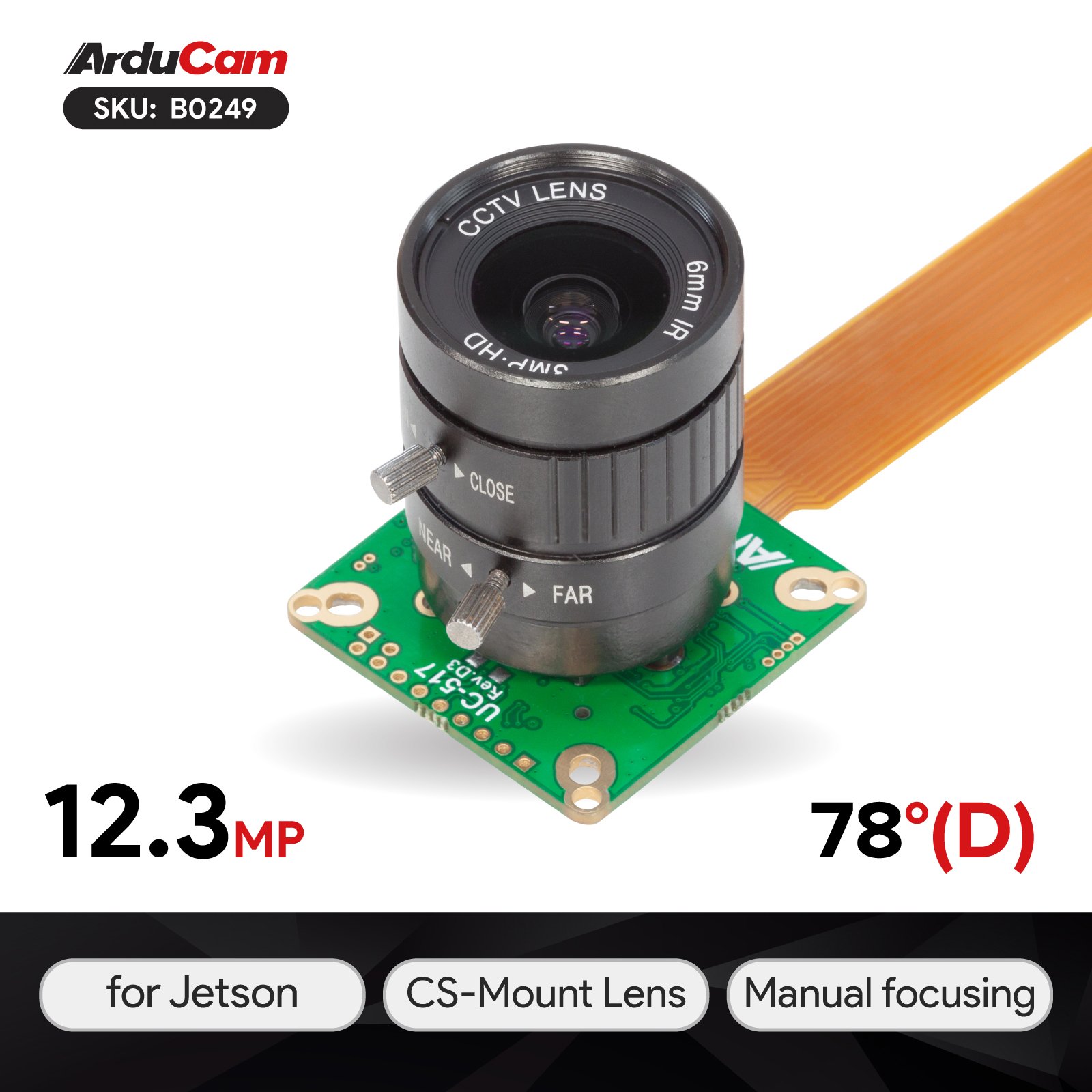
 www.arducam.com
IMX477 (High Quality Camera) for Jetson Nano and Xavier NX - Arducam
Improved 12MP Type 1/2.3 IMX477 camera module from embedded camera specialist Arducam - No need to remove resistors like RPi HQ cam, 6mm CS lens included.
KurtE
Senior Member+
Thanks, the keyword, I was missing was pass through... Found some samtec ones at Digikey.these are just header pins, possibly with pass-through. There’s a ton of different ones out there. The only thing that’s important is ofc the spacing. Looks like 2.54mm.
These are good examples, male and female. These are not passthrough tho. But those exist.
Know I am not Kurt but answer to your question is 10:
yep Note: 8 of them need to be contiguous for D0-7 and then two others for Pin clock and HSYNCI too, except - Except would be nice, to have some stuff actually work on Teensy boards. T4.1 has some support for it.I agree wholeheartedly with that
I too, except - Except would be nice, to have some stuff actually work on Teensy boards. T4.1 has some support for it.
Let’s make both work? Sort of a library that can work both with FlexIO on the Micromod and the MIPI CSI. Or two seperate libraries
I've started working on a little eLCDIF library: https://github.com/david-res/eLCDIF_t4
It's FAR from done, FAR from something functional, but I only started a couple hours ago.
I'm not making this super fancy or super flexible - I'm making the bare minimum that's needed to "easily" set it up"
I do want to shout out to @jmarsh for providing sample code for the eLCDIF, as I did use a fair bit of his code for the base of the library functions.
I can confidently say I wouldn't have been able to do anything anytime soon without it.
I'm at a bit of a loose end trying to decide which direction to go forward for video output.
I really don't want to get a screen with an RGB interface, would rather have generic output which means VGA or DVI/HDMI.
VGA requires either R2R ladders, which are reasonably cheap but messy (roughly 50 resistors for 24bpp) or a 3-channel VGA DAC like an ADV7123.
DVI requires an encoder such as a SiI164 (<$5) which also works for HDMI, or a proper HDMI encoder that can do audio as well like the ADV7513.
Yet another option is making a new USB device interface based on UVC that would basically make the Teensy look like a webcam to the USB Host. The drawback there is you need a PC or similar to view the output, and it wouldn't use any of the LCDIF stuff so it's really out of scope here.
I'm inclined to just go for the R2R solution, since it could be thrown together in an afternoon (assuming my local store actually has the right resistors, it's a new store I haven't visited since they opened) while the other ideas would require getting a board made... although if anyone else wanted to make a simple encoder board like that (basic digital RGB -> DVI/HDMI) I think they'd have no trouble covering their costs by selling extras back to the community.
mjs513
Senior Member+
Somebody did that already for uvc. Do a search on Boson or UVC - here is one of the links:Yet another option is making a new USB device interface based on UVC that would basically make the Teensy look like a webcam to the USB Host