Call to arms | Teensy + SDRAM = true

We’ve tested a wide range and a narrow range. The results says that 10pF or 12pF is probably the best caps. That’s allot more knowledge then we had before the tests.

Further testing is ideally tested by you Paul. My offer stands, there’s a board with your name on it. This way you get the testing exactly as you want. I still have caps from Mouser so those could be sent at the same time.

Until then I think these tests are completed.
Next on the list is the eLCD stuff that will be done by jmarsh and Rezo.
 
Another idea occurred to me while I was digging through old VGA cards looking for a DAC.
It was pretty common for video cards "back in the day" to have a VESA feature connector. They were mostly intended for connecting to accelerator cards, which would overlay their 3D rendering on the 2D frame generated by the basic graphics card. The interface they use is practically the same as the DOTCLK mode that the eLCDIF uses (hsync/vsync/pixel clock), which is also more or less the same as what the CSI (camera interface) can accept - meaning in theory it would be possible to turn a Teensy into a digital capture device, recording the output from a VGA card and acting as a USB camera to stream it to a connected PC.
 
@KurtE and I have been testing an OV7670 + spi displays (ili9341 and 9488). While testing the camera using extmem was getting what I would call halo effects:
09-42-19.png


Switching to the pixel buffer in DMAMEM that affect clears up drastically.
09-45-04.png


Maybe time for some one to test with cameras and the like for more application type testing.

Note: tried 133 and 166Mhz for the SDRAM. Also I am using @KurtE's variant version to get the added pins :)

Tried with using GPIO version and FlexIO version - seeing same thing.

@KurtE - feel free to add anything.
 
Does the camera deliver YUV data (rather than RGB) ? It looks like chroma/UV values are being significantly rounded somehow.
 
We are using the camera in RGB(565) mode,

We have the camera outputting DMA from FlexIO (I think only using one shifter right now). The camera returns the 16 bits, in byte swapped order, so we have a quick loop to swap them:
Code:
//byte swap
          for (int i = 0; i < numPixels; i++) pixels[i] = (pixels[i] >> 8) | (((pixels[i] & 0xff) << 8));
We then do a writeRect out of it to the screen
Code:
tft.writeRect(CENTER, CENTER, Camera.width(), Camera.height(), pixels);
 
If the only thing being changed is the location of the pixel buffer (DMAMEM vs SDRAM) so all the other code is exactly identical... maybe it's those BMCR0/BMCR1 register settings causing reads/writes to happen in the wrong order?
 
One other thing with the camera and the board I am using is that I had to add 4.7k pullups to SDA/SCL to get the camera to be detected reliably with the sdram board.
 
If the only thing being changed is the location of the pixel buffer (DMAMEM vs SDRAM) so all the other code is exactly identical... maybe it's those BMCR0/BMCR1 register settings causing reads/writes to happen in the wrong order?
Maybe. Not sure how to change or the like.

That it is why, I prefer to do more Random testing like this. We often find issues, that were not uncovered using standard tests.

One other thing with the camera and the board I am using is that I had to add 4.7k pullups to SDA/SCL to get the camera to be detected reliably with the sdram board.
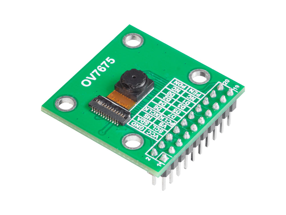
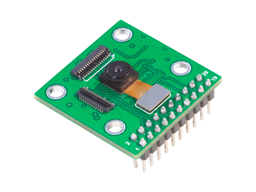
I have not run into this yet... But have in the past. Also have in the past run into issues where one or more of the jumper wires would come lose or the like, which is why when we were in the beta cycle for the T4.1 and later Micromod, created at least one test board that had the 2x9 pin pattern for the OV7670. I have not found my MicroMod one yet... Lost a lot of things after I organized my office several months ago. Now can not find anything.

If I were doing a board now, I would again probably put this or now the 2x10 connector, that one could experiment with these camera, as well as the Arduino OV7675:

Likewise the:

The 7675 arrived yesterday... Will try it out maybe sometime today. I just ordered the other one. Will first try them out on the GIGA, as the 7670 is working in my test sketch. Note: I used their SDRAM for the frame buffer. Which was pretty simple: Include the library...

Code:
 SDRAM.begin();
  Serial.println("Before camera start"); Serial.flush();
  if (!cam.begin(CAMERA_R640x480 /*CAMERA_R320x240 */, IMAGE_MODE, 10)) {
    blinkLED();
  }
  uint8_t *fb_mem = (uint8_t *)SDRAM.malloc(640 * 480 * 2 + 32);
  fb.setBuffer((uint8_t *)ALIGN_PTR((uintptr_t)fb_mem, 32));

Yesterday, I synced up my master branch of the Arduino_OV767X fork to the most recent Arduino branch, where the added in the OV7675 support. I am now merging that into my WIP branch for this. Still debugging

Just find it a lot easier when you are not fighting the wiring. Here are a few of the more recent released boards;
1707317136718.png

UR - Arduino GIGA with OV7670 and their display. Using my adapter board to rotate 90 degrees. Made it for the T4.1 testing
UL - T4.1 board with OV7670 (CSI) -
Center - this board, and rats nest of wires and logic probes, which keep falling off.
bottom - Pauls MMod test board for HiMax camera... Did not plug in the ILI9341, which goes into connector right of MMOD

Now back to playing. Not sure yet what...
 
@KurtE and I have been testing an OV7670 + spi displays (ili9341 and 9488). While testing the camera using extmem was getting what I would call halo effects:
View attachment 33189

Switching to the pixel buffer in DMAMEM that affect clears up drastically.
View attachment 33190

Maybe time for some one to test with cameras and the like for more application type testing.

Note: tried 133 and 166Mhz for the SDRAM. Also I am using @KurtE's variant version to get the added pins :)

Tried with using GPIO version and FlexIO version - seeing same thing.

@KurtE - feel free to add anything.
It would be super cool if you could film the display while moving the camera, to see how good the performance is.
I like the fact that the camera thing seems to have become the next project in the thread. Keep going :cool:

What is the global "standard" for high resolution/good cameras? And whatever protocol that is, can the Teensy handle it?
 
So far not much to film...Still trying to get things to work reasonably one frame at a time. As for moving it around to scan.

I am having a hard enough time with something like 16 wires on the connected to the camera, going to Devboard, where I plugged in Male to Male pins so the jumper wire has female end, but there is enough room to put in clips for Logic Analyzer, and not have some wire or probe come lose with out moving anything :LOL:

As for Good standard resolution ... camera hard to say what to suggest.
These are .3mp 640x480 max. But a lot of people mainly use these in the 320x240 mode.

The other one that is supposedly supported by Arduino GIGA (linked in previous post)
has resolution of 1616V x 1232H active pixel (2mp)
Not sure how feasible it would be to try to interface RPI compatible cameras.

But right now back to playing some.
 
I have an OV2640 that can do 1600x1200... it also does onboard MJPG compression, so the framerate isn't absolutely terrible at high resolutions. Supposedly the CSI can handle this.
Currently don't have any way to connect it to the devboard though since it's designed for an ESP32.
 
With all this cool stuff going on, could the Teensy output a HDMI signal and receive touch signals from a HDMI touch monitor?
 
With all this cool stuff going on, could the Teensy output a HDMI signal and receive touch signals from a HDMI touch monitor?
Think that was asked a couple times on the forum but I don't think it would be able to directly drive a HDMI screen. I did play with this thing:
a few years ago and it did work with a teensy 4 but you had to mod the software a bit
 
I know it can't do it directly, some sort of middleman could work just fine. But it would still be interesting if the Teensy could do it. I'll have to do some research.

@mjs513 did you get any decent performance?
 
The chips to convert RGB to DVI/HDMI seem surprisingly rare. There's a couple from Analog Devices but they're fairly expensive. Most projects seem to go for an FPGA instead.
 
The chips to convert RGB to DVI/HDMI seem surprisingly rare. There's a couple from Analog Devices but they're fairly expensive. Most projects seem to go for an FPGA instead.
Interesting, seems like there's a hole in the market. Or there's simply not people wanting such solutions.
In my head I'd love an IC or a board that does exactly that. Takes 8, 16, 24 bit lines and converts it to HDMI.
 
The following suggestion is certainly not the same as directly generating HDMI signals from the Teensy. However, acknowledging that some potential resolution may be lost, what about generating VGA signals (IIRC, already been done) & using one of the commonly available VGA-to-HDMI adapters for an alternate video output testbed ??

Mark J Culross
KD5RXT
 
Interesting, seems like there's a hole in the market. Or there's simply not people wanting such solutions.
In my head I'd love an IC or a board that does exactly that. Takes 8, 16, 24 bit lines and converts it to HDMI.
I would to. Like something based around the ADV7513, that takes basic RGB signals and I2S/SPDIF audio and outputs HDMI up to 1080p. But apparently there's issues getting HDMI encoders without a HDMI license, due to the mandatory content protection rubbish. DVI doesn't have that restriction and you can pretty much just feed those signals into a HDMI plug, but you lose audio support and all those designs are pretty much discontinued.
 
The following suggestion is certainly not the same as directly generating HDMI signals from the Teensy. However, acknowledging that some potential resolution may be lost, what about generating VGA signals (IIRC, already been done) & using one of the commonly available VGA-to-HDMI adapters for an alternate video output testbed ??
The resolution doesn't seem to be limited (at least up to 1080p) but the issue with VGA is that it's analog... so you either need a lot of resistors for an R2R ladder (roughly 17 for an 8-bit channel, times three channels) or a 3-channel high speed DAC... in which case you may as well go the extra mile and get a TMDS encoder instead.
 
I would to. Like something based around the ADV7513, that takes basic RGB signals and I2S/SPDIF audio and outputs HDMI up to 1080p. But apparently there's issues getting HDMI encoders without a HDMI license, due to the mandatory content protection rubbish. DVI doesn't have that restriction and you can pretty much just feed those signals into a HDMI plug, but you lose audio support and all those designs are pretty much discontinued.
Interesting stuff. Loosing the audio is bad ofc, but there are scenarios where only video is required. In such cases it should be possible then.
 
Here's a quick update from me:

Got some 5" and 4.3" LCDs here, 800*480px, 16.7M colors
@Dogbone06 sent over some Adaftuit 40 pin lcd breakout boards which arrived on Monday, got to wiring it up day before last, and started testing.
Consulted with @jmarsh about eLCDIF timing config, as I am using his sample code.

Loaded a static image from progmem, copied into SDRAM and pushed to the display

IMG_5105.jpg


And here is the original:
wallpapaer2.png


Yes the Blues and the Reds are swapped, but I suspect that is from the C array I generated

Next step, after confirming bus wiring is good, is to bind this to LVGL and see how it perfroms.
 
Back
Top