h4yn0nnym0u5e
Well-known member
Hi folks
I've been playing around with the PCM3168, a near-alternative to the CS42448 which is now shown as discontinued on Cirrus Logic's website. From a functionality point of view, the PCM3168 doesn't have the ability to add another pair of inputs via an auxiliary interface, so you're limited to 6 in 8 out, but otherwise it seems a fairly straightforward replacement.
From a software point of view, it works with the existing Audio TDM objects, barring the bug I recently found. I does of course need a control object, which can be found at https://github.com/h4yn0nnym0u5e/Audio/tree/feature/PCM3168
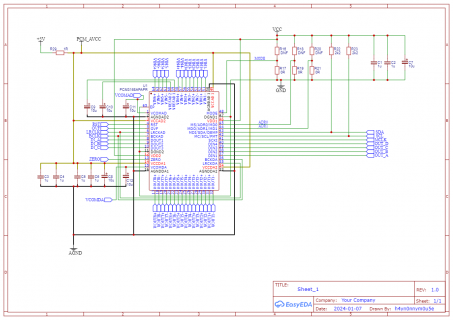
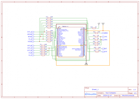
I've had 5 evaluation PCBAs built by JLCPCB, using the following schematic. I allowed for multiple options on which Wire and TDM interfaces to use, and the option to use I²S instead of TDM; as manufactured, it uses Wire and TDM2, which is all I've tested for now. The RST, ZERO and OVF pins are connected, but only RST is needed. The I²C address pins are also selectable - as-built it uses address 0x44.
PCM3168:

Teensy:

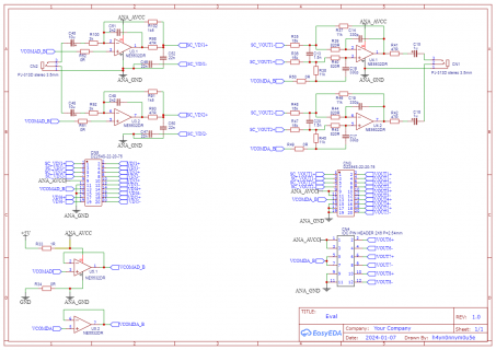
Analogue I/O:

The PCBA as built has several issues:
All that said, I probably don't need all 5 PCBAs, so I'm willing to let three go at cost (say £25 each inc. shipping) , ideally to people in the UK as I really don't fancy messing with Customs forms. I'm not interested in making any more, but I will post the Gerbers and (corrected) BoM if people want ... unless someone has the knowledge of how to make a project public on JLCPCB.
I've been playing around with the PCM3168, a near-alternative to the CS42448 which is now shown as discontinued on Cirrus Logic's website. From a functionality point of view, the PCM3168 doesn't have the ability to add another pair of inputs via an auxiliary interface, so you're limited to 6 in 8 out, but otherwise it seems a fairly straightforward replacement.
From a software point of view, it works with the existing Audio TDM objects, barring the bug I recently found. I does of course need a control object, which can be found at https://github.com/h4yn0nnym0u5e/Audio/tree/feature/PCM3168
I've had 5 evaluation PCBAs built by JLCPCB, using the following schematic. I allowed for multiple options on which Wire and TDM interfaces to use, and the option to use I²S instead of TDM; as manufactured, it uses Wire and TDM2, which is all I've tested for now. The RST, ZERO and OVF pins are connected, but only RST is needed. The I²C address pins are also selectable - as-built it uses address 0x44.
PCM3168:
Teensy:
Analogue I/O:
The PCBA as built has several issues:
- the analogue section doesn't work from the 5V supply: it needs ±12V connected to ANA_AVCC and ANA_AVMM
- fix by removing R53 and R34, and wiring a 5V -> ±12V DC-DC converter to the headers
- there's a track cut needed at U5 pin 4, and then that pin wiring to ANA_AVMM
- I messed up on the BoM, so many of the resistors are 100R rather than as-marked on the schematic
All that said, I probably don't need all 5 PCBAs, so I'm willing to let three go at cost (say £25 each inc. shipping) , ideally to people in the UK as I really don't fancy messing with Customs forms. I'm not interested in making any more, but I will post the Gerbers and (corrected) BoM if people want ... unless someone has the knowledge of how to make a project public on JLCPCB.