ADC tests for TCD1304DG

Oleum

Active member
For my TCD1304DG experiments I am testing the speeds of the ADC measurements.
I have now used the simplest ADC method, analogRead inside the void loop.
I was surprised that the processor clock rate has almost no influence on the sampling frequency.
I have a toggle output for my osci before and after the read command. The time difference is only about 145 ns . This surprises me, because the repetition frequency of the loop is about 55 KHz.
So the processor uses its time with "more important" things instead of serving me. Even if I insert a Serial.println(val) output into the loop, its frequency hardly changes.
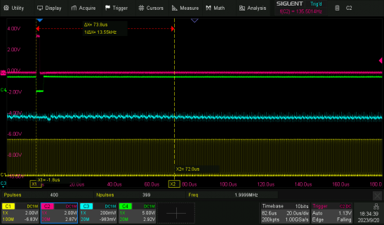
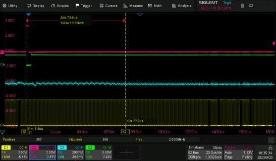
However, the serial output disturbs the timing every now and then, and the time difference increases sometimes from 145 to 222 ns.
I don't like this jitter so much. Actually, I want to couple a screen directly later to display my measured values (a spectrogram). Let's see how much time this will take. By the way, without analogRead the loop will run at 7.4 MHz. The time difference of the signals is then still 135 ns.

Do you think that another ADC method would be better?

How do I know that the ADC is already done with its measurement? Does the analogRead command wait or does it just show the last measurement?


Code:
constexpr int fMPin = 3;
constexpr int SH    = 5;

void setup()
{                
  //Serial.begin(38400);
 pinMode(fMPin, OUTPUT); 
pinMode(SH, OUTPUT);   
digitalWriteFast(fMPin,HIGH);
digitalWriteFast(SH,LOW);

}

int val;

void loop()                     
{

digitalToggleFast(SH);

  val = analogRead(0);
  //Serial.print("analog 0 is: ");
  //Serial.println(val);
  digitalToggleFast(fMPin);


}


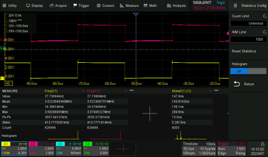
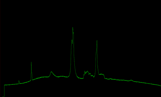
In the oscillogram you can see the two output signals, which are output before and after the ADC measurement (red and yellow). Their time difference of 145 ns would then be the time needed by the ADC. The actual frequency of the signals is the time the whole loop needs.
Since I toggle at each loop pass, the loop is of course twice as fast. Below in the screenshot you can see some statistics and histograms.
 

Attachments

  • ADCTest.png
    ADCTest.png
    78.5 KB · Views: 62
Each high time and low time of both of your signals is 1 conversion, so the actual conversion frequency is about 55 kHz. The program below gets the same result. analogRead() is part of the standard Arduino API. If you want more control over ADC conversion and the ability to use interrupts, etc., try the examples for the ADC library. You can start a conversion and then do other things until the conversion is complete (either poll or interrupt), then start another conversion, etc.

Code:
void setup() {
  Serial.begin( 9600 );
  while (!Serial) {}
}

void loop() {
  uint32_t count = 0;
  elapsedMillis ms = 0;
  while (ms < 1000) {
    analogRead(A0);
    count++;
  }
  Serial.println( count );
}
 
This is what I have so far. With a VB.Net test program I can actually already see the data of the photodiodes and display it as a curve.
Unfortunately, the AnalogRead function is so slow, that at the moment I only read every 16th diode, and on the next pass the next diodes. Always in the distance of 16 diodes. So 0,16,32... 2,17,33... 3,18,34 etc. I send these data so far as compound string "Number_of_DiodeSPACEAnalog_ValueCRLF".
In the VB program I split this string again the number of the diode is the index of an array, and the analog_value is the value.

What else can I do to make the reading of the analog value faster?
The AnalogRead would have 4 ticks available as a time period.

What other ways are there to make my program faster?
At the moment it runs with a clock of 816 MHz.


Code:
#include "TeensyTimerTool.h"

using namespace TeensyTimerTool;


static int cnt = 0;               // ticks of clock
static int diode = 0;             // index of diode
static int start = 32 * 4;        // startposition of active diodes
static int jump = 16 ;            // gap between two diodes to get enough time for analogread

int diodencounter ;             
int pass ;                        // number of passes along diodes

constexpr int fMPin = 3;          // clock-pin
constexpr int SH    = 5;          // SH-pin
constexpr int ICG   = 7;          // ICG-pin

bool flag = false;

// int val;
int Numberdiodes = 3648;
int volatile Dioden[3648];        // the array which will be filled every 'pass' while 'jump'ing from diode to diode


float Frequ = 135.5; // Hz        // the desired frequency
int F=int((1/Frequ)*4000000);

PeriodicTimer t;                  // the ticking timer

void setup()
{

// Serial.begin(115200);
Serial.begin(230400);
 // Serial.begin(38400);

  pinMode(fMPin, OUTPUT);   
  pinMode(SH, OUTPUT);   
  pinMode(ICG, OUTPUT);   

digitalWriteFast(fMPin,HIGH);     // startconditions
digitalWriteFast(SH,LOW);
digitalWriteFast(ICG,HIGH);


t.begin(callback, 250ns);         // callback every ...ns


}


void callback()
{

    digitalToggleFast(fMPin);                     // clock is ticking
    cnt++ ;                                       // next tick
    if (cnt >= 2 && cnt <= 10)                    // while tick is between 2 and 10
    {
        digitalWriteFast(SH,HIGH);                // SH is HIGH     
    }else {
    digitalWriteFast(SH,LOW);                     // all the other ticks SH is LOW
    }

   if (cnt >= 1 && cnt <= 20)                     // while tick is between 1 and 20
    {
        digitalWriteFast(ICG,LOW);                // ICG is LOW      
    }else {
    digitalWriteFast(ICG,HIGH);                   // all the other ticks ICG is HIGH

//   Explaining:
// We have multiple passes across the diodes. Since the AnalogRead command is too slow
// we have to wait. Therefore we read the diode that is jump away from the last diode.
// Only at the pass * jump(s) jump we pass the next diode. 'This is the way.'


  diodencounter = int(cnt/4);

    if (diodencounter >= start) {     // All starts with dummy pixels (start).  
      if((diodencounter % jump)== pass) {  //diodencounter Mod jump = pass?
          diode=((diodencounter-start) % (Numberdiodes-start));

          Dioden[diode] = analogRead(A8);
      }
  
      pass++ ;
      if(pass >= jump) {
        pass=0;
      }


    if (diode>=Numberdiodes){
          diode=0;
    }
    }
    }


if(cnt >= F){
  cnt=0;
  diode=0;
  digitalWriteFast(SH,LOW);
  digitalWriteFast(ICG,HIGH);

}

}


void loop(){                                    // Whole array send to SerialPort

for (int i = 0; i <= Numberdiodes; i++){
 Serial.print(i);
 Serial.print(" ");
 Serial.println(Dioden[i]);
}
}
 
Last edited:
What else can I do to make the reading of the analog value faster?

The program below shows three methods of doing analog read. You can get more than 10x faster by using the ADC library. You can also use the ADC library in asynchronous mode, either by starting a conversion, doing something else, check for conversion complete, etc., or by using interrupts, where you get an interrupt on conversion complete.

*ADC_METHOD == 0 ---> 55 ksps this is the default (what you are doing now)
*ADC_METHOD == 1 ---> 199 ksps analogReadAveraging(1) reduces average from 4 readings to 1 (fastest)
*ADC_METHOD == 2 ---> 655 ksps use ADC library and set conversion speed, etc.

Code:
#include <ADC.h>       // ADC library by pedvide

ADC *adc;              // ADC object

#define ADC_METHOD (2) // 0=default, 1=average(1), 2=library

void setup()
{
  Serial.begin(9600); // USB speed is always the same (baud rate doesn't matter)
  while (!Serial) {}

  if (ADC_METHOD == 0) {           // use default averaging of 4 samples
  }
  else if (ADC_METHOD == 1) {      // reduce from default 4 to 1    
    analogReadAveraging( 1 ); 
  }
  else if (ADC_METHOD == 2) {      // use ADC library
    adc = new ADC();
    // configure ADC0
    adc->adc0->setReference( ADC_REFERENCE::REF_3V3 );    // internal 3.3V ref
    adc->adc0->setAveraging( 1 );                         // samples per reading
    adc->adc0->setResolution( 12 );                       // bits of resolution
    adc->adc0->setConversionSpeed( ADC_CONVERSION_SPEED::HIGH_SPEED );
    adc->adc0->setSamplingSpeed( ADC_SAMPLING_SPEED::MED_SPEED );
  }
}

elapsedMillis ms;
uint16_t adc_value;
uint32_t readCount, readCountPrev;

void loop() {                                    
  if (ADC_METHOD == 0 || ADC_METHOD == 1) {
    adc_value = analogRead(A8);
  }
  else if (ADC_METHOD == 2) {
    adc_value = adc->adc0->analogRead(A8);
  }
  readCount++;
  if (ms >= 1000) {
    Serial.printf( "%8lu\n", readCount - readCountPrev );
    readCountPrev = readCount;
    ms -= 1000;
  }
}
 
I have now made a few tests with the three methods. Unfortunately I always get disturbances from 130µs on, as soon as AnalogRead is called.

Yellow is the disturbed clock signal
 

Attachments

  • WithoutRead.png
    WithoutRead.png
    82.5 KB · Views: 52
  • ReadMeth_0_1_2.png
    ReadMeth_0_1_2.png
    83.8 KB · Views: 46
You didn't show your code this time, but in your previous program, you have a 250-ns timer (4 MHz), and you are calling analogRead() from the callback. analogRead() takes much longer than 250 ns to execute, so that's going to be a problem. Let's say it takes 20 us for analogRead() to return. That means your program will miss 4*20=80 timer interrupts, and that will definitely disturb your clock signal.
 
If I can't generate the signals with the Teensy without being disturbed, I guess I have to use an external generator.

Code:
#include "TeensyTimerTool.h"
#include <ADC.h>

ADC *adc;

using namespace TeensyTimerTool;


static int cnt = 0;         // ticks of clock
static int diode = 0;       // index of diode
static int start = 16 ;// 32 * 4;  // startposition of active diodes in ticks  128 ticks = 64 µs
static int jump = 16;       // gap between two diodes to get enough time for analogread

int diodencounter;
int pass;  // number of passes along diodes

constexpr int fMPin = 3;  // clock-pin
constexpr int SH = 5;     // SH-pin
constexpr int ICG = 7;    // ICG-pin

bool flag = false;

int Numberdiodes = 3648;
int volatile Dioden[3648];  // the array which will be filled every 'pass' while 'jump'ing from diode to diode


float Frequ = 135.5;  // Hz        // the desired frequency
int F = int((1 / Frequ) * 4000000);

PeriodicTimer t;  // the ticking timer

void setup() {

   //Serial.begin(115200);
   Serial.begin(230400);
  // Serial.begin(38400);

  pinMode(fMPin, OUTPUT);
  pinMode(SH, OUTPUT);
  pinMode(ICG, OUTPUT);

  digitalWriteFast(fMPin, HIGH);  // startconditions
  digitalWriteFast(SH, LOW);
  digitalWriteFast(ICG, HIGH);


  adc = new ADC();

   analogReadAveraging(1);

  // Methode 2
  // adc->adc0->setReference( ADC_REFERENCE::REF_3V3 );    // internal 3.3V ref
  // adc->adc0->setAveraging( 1 );                         // samples per reading
  // adc->adc0->setResolution( 11);                       // bits of resolution
  // adc->adc0->setConversionSpeed( ADC_CONVERSION_SPEED::HIGH_SPEED );
  // adc->adc0->setSamplingSpeed( ADC_SAMPLING_SPEED::MED_SPEED );


  t.begin(callback, 250ns);  // callback every ...ns
}


void callback() {

  cnt++; // next tick

  digitalToggleFast(fMPin);   // clock is ticking
                       
  if (cnt >= 2 && cnt <= 8)  // while tick is between 2 and 10
  {
    digitalWriteFast(SH, HIGH);  // SH is HIGH
  } else {
    digitalWriteFast(SH, LOW);  // all the other ticks SH is LOW
  }

  if (cnt >= 1 && cnt <= 16)  // while tick is between 1 and 20
  {
    digitalWriteFast(ICG, LOW);  // ICG is LOW
  } else {
    digitalWriteFast(ICG, HIGH);  // all the other ticks ICG is HIGH
  }

    read();

  if (cnt >= F) {
    cnt = 0;
    diode = 0;
    digitalWriteFast(SH, LOW);
    digitalWriteFast(ICG, HIGH);
  }
}


void read() {

  diodencounter = int(cnt / 4); // Die Diodennummer berechnen

  if (diodencounter >= start) {            // All starts with dummy pixels (start).
    if ((diodencounter % jump) == pass) {  //diodencounter Mod jump = pass?
      diode = ((diodencounter - start) % (Numberdiodes - start));

      Dioden[diode] = analogRead(A8);
      // Dioden[diode] =adc->adc0->analogRead(A8);
    }

    pass++;
    if (pass >= jump) {
      pass = 0;
    }


    if (diode >= Numberdiodes) {
      diode = 0;
    }
  }
}


void loop() {  // Whole array send to SerialPort
  // read;
  for (int i = 0; i <= Numberdiodes; i++) {
    Serial.print(i);
    Serial.print(" ");
    Serial.println(Dioden[i]);
  }
}
 
If I can't generate the signals with the Teensy without being disturbed, I guess I have to use an external generator.

You can generate the signals in the callback, but you can't call analogRead() from the callback. I'm not sure what you're trying to do, so I can only make general suggestions. In your callback function, instead of calling analogRead(), set a flag that indicates it is time to do an analog read, and change your loop() to something like this. You probably will need a different method of keeping track of which diode you are reading, but the key thing is NOT to call analogRead() from your timer callback. This way, the timer callback can keep executing every 250 ns.

Code:
void loop() {  // Whole array send to SerialPort
  if (readFlag == true) {
    Dioden[diode] = analogRead(A8);
    Serial.print(diode);
    Serial.print(" ");
    Serial.println(Dioden[diode]);
    readFlag = false;
  }
}
 
Thank you, I will try this again. As far as I remember I had already tried to do the AnalogRead in the void loop. I will try that with the flag.
 
What is wrong with my code.
I noticed strange effects on the oscilloscope. With a period of several seconds my clock signal breaks down.
I noticed this only by chance, normally I didn't pay attention to such late signals at all. No matter if I toggle the output or set it HIGH or LOW respectively, I don't get a steady voltage.
I have removed everything else from the code. Only the timer and the switching of the output are still running.

Code:
#include "TeensyTimerTool.h"
using namespace TeensyTimerTool;

constexpr int fMPin = 3;  // clock-pin
bool tog =false;

PeriodicTimer t;  // the ticking timer

void setup() {

  pinMode(fMPin, OUTPUT);
  digitalWriteFast(fMPin, HIGH);  
  t.begin(callback,500ns);  // callback every ...ns

}


void callback() {
 tog = !tog;

if(tog){
digitalWriteFast(fMPin, HIGH);
}
else {
digitalWriteFast(fMPin, LOW);
}

}


void loop() {  

  
}
 

Attachments

  • NotTog.png
    NotTog.png
    55.2 KB · Views: 62
Your program seems okay, so my first guess would be that you have a measurement issue. Can you take a step back and tell us what you are trying to do, and why you are producing this 1 MHz square wave with a digital output instead of using the T4.1 PWM capabilities?
 
I noticed strange effects on the oscilloscope. With a period of several seconds my clock signal breaks down.
Yes, your scope is playing tricks on you. Your scope's sample frequency (2MSa/s) is very close to exact 2x your 1MHz signal (something to do with Nyquist...).
Using your code, this is how my scope's picture looks when the signal is sampled at 10MSa/s:

SDS00091.png


BTW: did you know about digitalToggleFast()? Your code would look like this:
Code:
#include "TeensyTimerTool.h"
using namespace TeensyTimerTool;

constexpr int fMPin = 3;  // clock-pin

PeriodicTimer t;  // the ticking timer

void setup() {
  pinMode(fMPin, OUTPUT);
  digitalWriteFast(fMPin, HIGH);
  t.begin(callback, 500ns); // callback every ...ns
}

void callback() {
  digitalToggleFast(fMPin);
}

void loop() {
}

Paul
 
Thanks @PaulS.
I just hooked my analog oscilloscope to the signal and I don't see any interruptions in the voltage.
I actually hadn't thought of the effect you mentioned here.
My digital Osci should have
Bandwidth: 100 MHz
Channels: 4 CH
Real time sampling rate: 2 GSa/s
Capture rate: 120,000 wfm/s
Memory depth: 200 Mpts

I had already used the toggle option. Here I had only explicitly switched to HIGH and LOW to get a better control over the ratio.

It is still about the project mentioned here:
https://forum.pjrc.com/threads/73502-Transfer-to-PC

I do get the data into my PC, but unfortunately reading out the analog measurement happens too rarely.
That's why I'm looking for where I can make improvements in my Teensy program.
 
I do get the data into my PC, but unfortunately reading out the analog measurement happens too rarely.
That's why I'm looking for where I can make improvements in my Teensy program.
Did you perhaps see this thread? Especially message #21 where forum member ntyrell seems to have it working on a Teensy 4.0: "i have precise timing control over everything".

Paul
 
Yes, I had seen this post before. But unfortunately I am quite a beginner when it comes to C++ and Teensy. For this reason I don't understand the program described there at all.
I could possibly copy it, but I would not learn anything from it.
 
You have chosen a challenging problem, one that may not have a workable solution by direct manipulation of digital I/O. If you want to learn more about C++, perhaps work through examples in various libraries and online tutorials? That might allow you to go back to the flexPWM solution to this problem. Starting from a working program is sometimes a better way to learn than starting from scratch.
 
I am now quite satisfied with the development of my spectrometer.
The program examples that I found here or on the Internet didn't help me much because I didn't understand most of them.
I don't read out the chip's pixels linearly because I couldn't do this at the speed specified by the chip. That's why I let a random time elapse after transferring the data to the PC.
This means that the pixel data is also sent to the PC in a random pattern. But that doesn't really bother me.

So far I have transferred the data as strings.
The diode number, a space, then the measured value + CRLF.
This is done via the virtual serial interface. I have read that Teensy is also able to send the data directly to the PC via USB.
Would that increase the speed?
(The programming effort for this seems a bit high to me).
 

Attachments

  • DayLightLamp.PNG
    DayLightLamp.PNG
    20.5 KB · Views: 16
In preface, using the TCD1304 (or any CCD), and obtaining results that are useable, at least reproducible and proportional to your light input, is not trivial.

Here are some of the issues: (A) light corruption vs "keep clean" and interference with readout and transfer, (B) matching the ADC and handling kickback, (C) timing if you want triggerd or gated scans, (D) part-to-part variances for source impedance and voltage offset, and numerous etc. There really is a lot to it.

You can find a complete design that we feel does a pretty good job and a descrtion of the issues in some detail here: TCD1304 - complete. (There is a sketch there, use it if you like)

Now for some specific comments or suggestions (if you really want to roll your own):

#1 Clock and readout - you will do much better to operate the SH, ICG and the ADC loop, from interrupt handlers which you connect to a clock (see the above link).

#2 If you want fast frame rates, or short exposure times, then you might want to stay with binary transfers. The T4 is especially good for this because of the faster USB. See the next item.

#3 Spooky non-linear response to changing the exposure time - Note carefully!! - the words "electronic shutter" in the datasheet, do not mean a shutter in the conventional sense of a shutter.

The device continues to receive light while you loop over the ADC and/or transfer data to the host. If this is not managed correctly, the signal level you read from the device might not correspond to what you think was your exposure time.

If you need a short exposure time, this becomes a little bit tricky on an MCU (rather than progammable logic), because clocking the SH pin which is the only way to clear the buckets, may compete for a resource that you need in your ADC loop.

See the above link for more on this subject and some scenarious where it is less of an issue.

#4 Spooky ADC behaviors If you want qualitative results, use an opamp follower and RC before the input to the ADC input on the Teensy. This has to do with kickback from SAR digitizer. (If I had a nickel for evertime somebody told me all the MCU ADC's are flakey....)

Again, see the above link.

#5 How many bits do I actually use/need? The 600mv range of the TCD1304 by itself, means that you will only have 8 bit data with the T4. We might ask, "since the TCD1304 range is 2mV dark to 600mV saturation, why do I need more than 8bits?" It makes a difference when you want to work with lower light levels, for example by adding a lot of frames to build up the S/N.

And yet again, see the above link.
 
Last edited:
One thing I should correct, or be more clear about:

With the master clock at 2MHz, you read the device at 500KS/s, or about 8 msecs per frame.

For the T4 with its 480 Mb/s USB, the readout from the sensor should be what sets your maximum frame rate.
 
Back
Top