can't get attachInterrupt to work on Teensy 4.0

Status
Not open for further replies.

phydoughsbuddy

New member
I recently purchased a Teensy 4.0 and am looking forward to using it in a project I am working on. I had been trying to implement the project on an Arduino, but the 16MHz clock speed created severe limitations. In general, I am attempting to read the pulses from an OMRON E6B2-CWZ6C Rotary Encoder 1024P/R 5-24V and calculate the speed that it is rotating, then use the RPM value for other processes. I am doing the coding on a Windows machine (Windows 10) in an Arduino/Teensyduino(1.48) environment I have already worked out the details of the RPM calculation from my previous work with the Arduino – so, that part is not the issue. The part that I am having problems with is getting the attachInterrupt function to work. The rotary encoder is powered by a 5 volt source, and outputs a 5 volt signal. I am translating that signal to 3.3 volts to be compatible with the Teensy input limitations. I have used an oscilloscope to verify the 5 volt output from the encoder and the 3.3 translated voltage that I am sending to digital pin 2 on the Teensy. I am not receiving any output on pin 4 (motorStep) of the Teensy. It seems like it ought to be fairly straight forward, but nothing I have tried has worked. I have exhausted all the online information that I can find and decided to call out for help. Below is an abbreviated code listing that focuses on the interrupt handling only.


#define encoderA 2 // rotary encoder output A (triggers interrupt) = pin 2
#define encoderB 7 // rotary encoder output B (to determine forward or reverse) = pin 7

#define motorStep 4 // motor step = pin 4
#define motorDirection 5 // motor direction = pin 5


void setup() {

pinMode(encoderA, INPUT_PULLUP);
pinMode(encoderB, INPUT_PULLUP);
pinMode(motorStep, OUTPUT);
pinMode(motorDirection, OUTPUT);

attachInterrupt(digitalPinToInterrupt(encoderA), encoderISR, FALLING); // pin 2

}// end setup


void loop() {

}// end loop


void encoderISR(){

digitalWrite(motorStep, HIGH);
digitalWrite(motorStep, LOW);

}// end encoderISR
 
Hi,
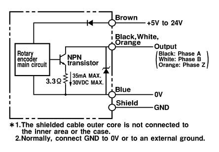
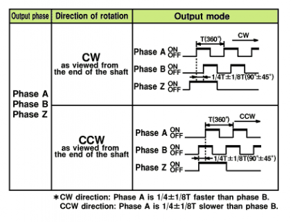
The spec page of the Omron rotary encoder shows this:
Enc1.png Enc2.png

You stated
The rotary encoder is powered by a 5 volt source, and outputs a 5 volt signal. I am translating that signal to 3.3 volts to be compatible with the Teensy input limitations.

Since the encoder output pin is an open collector, I don't think it actually outputs 5V.
You only need to pullup that pin [which you do by "pinMode(encoderA, INPUT_PULLUP);"] and then read the pin. No additional logic needed.
I'm wondering what you mean by 'translating'?

To check whether "attachInterrupt" works correctly, I wrote this small sketch:
Code:
#define encoderA 2
#define encoderB 3
int ledState = LOW;

void setup() {
  pinMode(LED_BUILTIN, OUTPUT);
  pinMode(encoderA, INPUT_PULLUP);
  attachInterrupt(digitalPinToInterrupt(encoderA), encoderISR, FALLING);
}

void loop() {
}

void encoderISR() {
  ledState = !ledState;                   // toggle the LED with every entry into the ISR
  digitalWrite(LED_BUILTIN, ledState);
}

I connected a simple EC11 rotary encoder to pin 2 and 3 and watched the builtin LED for flashing while rotating the encoder: it did. So "attachInterrupt' is functional.

Hope this helps,
Paul

PS: I'm on Arduino 1.8.10, Teensyduino 1.49b4.
 
Recommend trying the Encoder library. Even if you want to write your own code from scratch, at least click File > Examples > Encoder > Basic to have a known-good program for the sake of comparison. This could help you verify your hardware is indeed good, before pouring so much time into your own code.

One common mistake is to use pinMode after attachInterrupt. Your abbreviated code shows it before, so probably not an issue?
 
The output pulse
Code:
void encoderISR(){

digitalWrite(motorStep, HIGH);
digitalWrite(motorStep, LOW);

}// end encoderISR
might be to short, so perhaps some kind of delay or simply toggle the output in the ISR.
 
Thank you for your quick response. I ran the sketch you sent and confirmed that attachInterrupt was indeed working on my Teensy 4.0. Sorry for the false alarm. I had been trying to do something similar to what your sketch does, but using an external LED (attached to pin 4) and setting that pin HIGH and LOW – the problem was the transition was so quick that it was not visible to the human eye. Just to clear up any omissions from my original post, I am using 10K pullup resistors on the outputs of the rotary encoder and I am using a bi-directional logic level shifter that I purchased on EBay to do the voltage level translations. Thank you, once again
 
The nice thing about the open-collector outputs of the OMRON E6B2-CWZ6C Rotary Encoder 1024P/R, is that you don't need 10K pullups resistors and/or logic level shifters.
Just connect the output pins of the decoder directly to the Teensy pins without any additional parts.
These commands will pullup the signal internally on the Teensy to 3V3:
Code:
pinMode(encoderA, INPUT_PULLUP);
pinMode(encoderB, INPUT_PULLUP);
And this command will thus read the pin at the correct voltage level of 3V3:
Code:
attachInterrupt(digitalPinToInterrupt(encoderA), encoderISR, FALLING); // pin 2

This saves some parts...
Paul
 
Status
Not open for further replies.
Back
Top