DIy board on 3.3v

theboot900

Well-known member
Hi Paul.

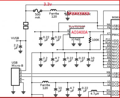
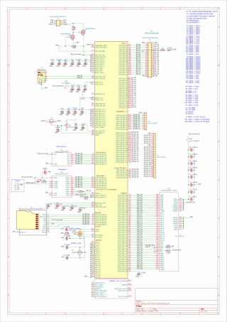
On a DIY board to go exclusively powered by 3.3v, would this work?

VIN would be 3.3v This would go into USB1_VBUS and USB2_VBUS. Is 3.3v enough to drive these?

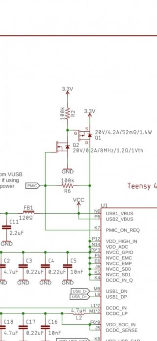
In place of the 3.3v regulator in the circuit. If i changed that to a NPN MOSFT AO3400A. Vin goes through here. (Gate voltage of 0.7 to 1.0v). This should be toggled by PMIC_ON_REQ

Would i still need the PNP DMG2305UX. Is this used for some kind of soft start or reverse polarity protection?
 

Attachments

  • Screenshot_20250131_104900_Dropbox.jpg
    Screenshot_20250131_104900_Dropbox.jpg
    150.2 KB · Views: 7
G
Look at the 2 transistor circuit Sparkfun's MicroMod Teensy uses.

Thanks Paul.

Do you know what transistors are used for Q1 and Q2?

I'm struggling to work out the sequence from Q1 to Q2 and PMIC

From my understanding we need power on USB_VBUS to get 1.1v output on PMIC. I don't see anything like that on there schematic
 

Attachments

  • Screenshot_20250131_155029_Gallery.jpg
    Screenshot_20250131_155029_Gallery.jpg
    64.9 KB · Views: 9
I'm not sure exactly which transistors they are using. Probably best to ask them. But when MicroMod was in development, I had recommended using DMG1012T for Q2. Main issue is you want the Vgs(th) max spec to be no more than 1V, so it's guaranteed to turn on. Specs for Q1 are less critical, almost any P-channel part meant for 3.3V gate drive ought to work.
 
Thanks!
Q1 is DMG2305UXQ-7
Q2 is RUE002N02TL

So final question. Supplying 3.3v to USB1_VBUS and USB2_VBUS must be enough to get the whole process working?

And USB communication/serial still works with 3.3v on Vbus?
 
So while im waiting for the correct flashmem to arrive to run Dogbones Board i've designed a 4 layer board with SDram using the BGA 12x12 chip (Thanks Dogbone for the memory connection schematic).

I've managed to get the dimensions at 60mm x 36mm (About the same length as Teensy 4.1 but double the width)

The idea is to be able to solder it yourself (If your comfortable with BGA soldering) - ive used 0603 components. I've also put all the components (except some capacitors) on one side. I've also got a list with mouser links for all the components.

Its got SDCard and pin out for RTC battery backup. I've pretty much exposed every pin possible. It's just using a standard Micro USB connector for simplicity. There's no regulator on board so it needs to be supplied with a stable 3.3v (I think ive copied the schematic of the Micromod correctly. I'm hoping i've got the startup power sequence correct)

When i get it on my next pcb order and i can verify it all works ill upload the files.

*edit* schematic image compressed. This is better
 

Attachments

  • Capture.png
    Capture.png
    450 KB · Views: 8
  • Capture2.png
    Capture2.png
    669.6 KB · Views: 7
  • Capture3.PNG
    Capture3.PNG
    414.6 KB · Views: 7
  • Capture4.PNG
    Capture4.PNG
    296 KB · Views: 8
  • Schematic-1.png
    Schematic-1.png
    688.7 KB · Views: 8
Last edited:
Back
Top