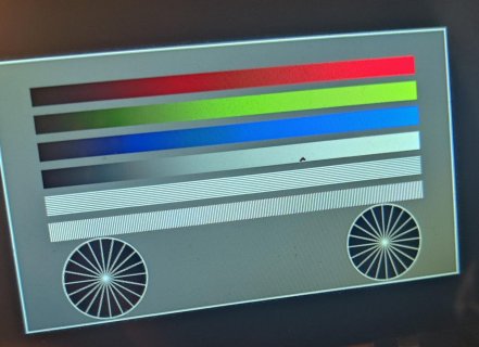
Hello. I have this Riverdi 4.3" capacative display. Datasheet link. BT817 chip programming guide.
I have used the Riverdi ardunio uno shield with this riverdi sample app/program to start. This one is similar to the Rudolf library. I also was able to successfully make this sample program into one that works for my uno (adding a temp sensor, an external button, my own display lists of menus/touch options, etc).
I want to use this on my 4.1 so I can add more sensors/do more than how restricted I am using the uno and its add-on shield, but I get errors when I connect this display to my 4.1, and I do not really understand these errors.
I tried to follow this post here, but was unsuccessful in my attempts.
I used this 20pin display cable breakout board to connect it to my teensy.
This is how I connected it to my 4.1
For the 4.1, I cut the power line from the microUSB to usb and power the 4.1 (and any other periphereal) via my PSU.
The main errors I get when I connect this and try to compile this from the arduino IDE (new and old versions):
1. buffer and prog_uchar errors
2. GPIO_CS and GPIO_PD errors
Link to Gpu_Hal.h prog_uchar8_t and buffer error location
Link to the CS/PD error location
Link to the platform.h file (where the board specs are configured)
1. My plan is to tinker around with the erorrs and see if I can figure out how to intialize this program for my teensy 4.1; I think it's with the platform.h file.
2. Otherwise, I saw this GDSTx library often in the thread I linked above and will try to use my 4.1 with it.
3. There is another riverdi example for this display just for the esp32 so I can look up how to flash the program w/o relying on the arduino environment.
Thanks for any input in advance. Let me know if you need any more info.
I have used the Riverdi ardunio uno shield with this riverdi sample app/program to start. This one is similar to the Rudolf library. I also was able to successfully make this sample program into one that works for my uno (adding a temp sensor, an external button, my own display lists of menus/touch options, etc).
I want to use this on my 4.1 so I can add more sensors/do more than how restricted I am using the uno and its add-on shield, but I get errors when I connect this display to my 4.1, and I do not really understand these errors.
I tried to follow this post here, but was unsuccessful in my attempts.
I used this 20pin display cable breakout board to connect it to my teensy.
This is how I connected it to my 4.1
| display/breakout | 4.1 |
| 3 SPI_SCLK | 13 |
| 4 MISO | 12 |
| 5 MOSI | 11 |
| 6 CS | 10 |
| relevant 3.3v logic/5vbacklights/gnds correctly connected to psu |
For the 4.1, I cut the power line from the microUSB to usb and power the 4.1 (and any other periphereal) via my PSU.
The main errors I get when I connect this and try to compile this from the arduino IDE (new and old versions):
1. buffer and prog_uchar errors
2. GPIO_CS and GPIO_PD errors
Link to Gpu_Hal.h prog_uchar8_t and buffer error location
Link to the CS/PD error location
Link to the platform.h file (where the board specs are configured)
- Gpu_Hal.h:309:65: error: 'prog_uchar8_t' has not been declared and Gpu_Hal.h:309:80: error: section attribute not allowed for 'buffer'
-
Code:
void Gpu_Hal_WrCmdBufFromFlash(Gpu_Hal_Context_t *host, PROGMEM prog_uchar8_t *buffer,uint32_t count); - many errors involving the buffer "section attribute" and "prog_uchar8_t"
-
- App_Common.cpp:253:9: error: 'prog_uchar8_t' does not name a type; did you mean 'prog_uchar'?
253 || ^~~~~~~~~~~~~Code:PROGMEM prog_uchar8_t logo_graphics[6224] = {
| prog_uchar- ****** I don't use this logo/image map in my program. This is a default included one for the sample.
- Gpu_Hal.cpp:49:11: error: 'GPIO_CS' was not declared in this scope
49 |Code:pinMode(GPIO_CS, OUTPUT); - Gpu_Hal.cpp:52:11: error: 'GPIO_PD' was not declared in this scope
52 |Code:pinMode(GPIO_PD, OUTPUT);
1. My plan is to tinker around with the erorrs and see if I can figure out how to intialize this program for my teensy 4.1; I think it's with the platform.h file.
2. Otherwise, I saw this GDSTx library often in the thread I linked above and will try to use my 4.1 with it.
3. There is another riverdi example for this display just for the esp32 so I can look up how to flash the program w/o relying on the arduino environment.
Thanks for any input in advance. Let me know if you need any more info.


