
You are using an out of date browser. It may not display this or other websites correctly.
You should upgrade or use an alternative browser.
You should upgrade or use an alternative browser.
Guitar input to Audio Shield.
- Thread starter TonyAme
- Start date
Really, no need for any buffer?It will work straight into the audio shield, if you just want mess around with it - like Pio's stereo guitar emulator. It might have to some high end roll off, though.
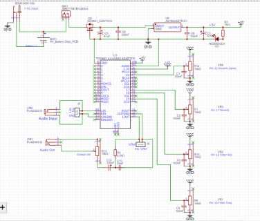
Also, I have a passive filter circuit for the output as in the schematic attached, does it need to be connected to Out Gnd?
Thanks very much,
Tony
Last edited:
A guitar with active pickups will have the buffer is already built in. Otherwise, i'd recommend a HiZ buffer.
Plenty projects are available online. I've made a simple stereo buffer project which can be soldered on a perf board:

 github.com
Since your output is mono, you could use one buffer channel for the input and the second after the OutputVolume pot. This way the pedal will have proper instrument HiZ input and a constant low impedance output.
Filter connection is correct. OUTGND, LINGND, RINGND are the same signal. The only "different" ground is the one used for headphone output.
Plenty projects are available online. I've made a simple stereo buffer project which can be soldered on a perf board:
TGX4/diy_buffer.md at main · hexeguitar/TGX4
Tennsy4 based guitar amp emulator. Contribute to hexeguitar/TGX4 development by creating an account on GitHub.
github.com
Since your output is mono, you could use one buffer channel for the input and the second after the OutputVolume pot. This way the pedal will have proper instrument HiZ input and a constant low impedance output.
Filter connection is correct. OUTGND, LINGND, RINGND are the same signal. The only "different" ground is the one used for headphone output.
BillFM
Well-known member
@TonyAme, be aware that you can't connect 5volts from USB at the same time as 5V from regulator. They will fight each other. there are multiple solutions to this issue.
You could add a jumper plug/pins to the 5V regulator output. Remove jumper when using USB to program Teensy. However, this is prone to forgetting to remove the jumper.
You could add 2 diodes to form a diode OR'ing circuit. 1 diode is at the output of 5V regulator. The other diode is placed on bottom of Teensy as shown at PJRC page: Using External Power and USB (shown for a different Teensy family, but same procedure). Don't cut the pcb track too deep or else you could penetrate into the inner pcb layer copper. Go slow and check with multi-meter that the track is cut. The diode OR'ing is pretty foolproof in usage.
You can cut the USB cable 5V wire. Just don't mix up your USB cables and plug in a cable that isn't cut. Prone to mistakes.
We can't see your entire schematic, but I would suggest you add a Bypass switch to the design.
BTW, most guitar pedals (but not all) use a -ve center pin for power adaptors. Make sure whatever adaptor you are using matches your +ve center pin design.
Good luck with your project. Let us know how it all worked out.
Thanks very much for that great info. I won't be using the usb port for power. This schematic is a preliminary design, but yes a bypass switch and a negative center power adapter plug is the electric guitar way to go. Appreciate the help, thank you.@TonyAme, be aware that you can't connect 5volts from USB at the same time as 5V from regulator. They will fight each other. there are multiple solutions to this issue.
You could add a jumper plug/pins to the 5V regulator output. Remove jumper when using USB to program Teensy. However, this is prone to forgetting to remove the jumper.
You could add 2 diodes to form a diode OR'ing circuit. 1 diode is at the output of 5V regulator. The other diode is placed on bottom of Teensy as shown at PJRC page: Using External Power and USB (shown for a different Teensy family, but same procedure). Don't cut the pcb track too deep or else you could penetrate into the inner pcb layer copper. Go slow and check with multi-meter that the track is cut. The diode OR'ing is pretty foolproof in usage.
You can cut the USB cable 5V wire. Just don't mix up your USB cables and plug in a cable that isn't cut. Prone to mistakes.
We can't see your entire schematic, but I would suggest you add a Bypass switch to the design.
BTW, most guitar pedals (but not all) use a -ve center pin for power adaptors. Make sure whatever adaptor you are using matches your +ve center pin design.
Good luck with your project. Let us know how it all worked out.
Thank you. Will check out your stereo buffer, appreciate it.A guitar with active pickups will have the buffer is already built in. Otherwise, i'd recommend a HiZ buffer.
Plenty projects are available online. I've made a simple stereo buffer project which can be soldered on a perf board:
TGX4/diy_buffer.md at main · hexeguitar/TGX4
Tennsy4 based guitar amp emulator. Contribute to hexeguitar/TGX4 development by creating an account on GitHub.
Since your output is mono, you could use one buffer channel for the input and the second after the OutputVolume pot. This way the pedal will have proper instrument HiZ input and a constant low impedance output.
Filter connection is correct. OUTGND, LINGND, RINGND are the same signal. The only "different" ground is the one used for headphone output.
I'll be removing the Teensy + audio board from the circuit whenever I program the Teensy. Is there something I'm not seeing in my schematic concerning the 5V input from the 7805 regulator? (I do often not notice obvious things when constantly looking at the same schematic for a long time.) Please let me know if that's happening here...lolSo..., how do you intend to program Teensy?
Turning switch SW1 OFF is not a solution. Regulators don't like seeing 5V applied to their output pin.
You should isolate the regulator 5V output from the USB 5V source.
I appreciate it.
"Regulators don't like seeing 5V applied to their output pin." <--- this is good to know in case I do decide to do in-circuit programming, I did not know this.
Last edited:
BillFM
Well-known member
Okay. Removing Teensy+Audio board from circuit for programming will work.
The down side of doing that is..., potential damage to Teensy.
Please don't use a screw driver to pry it off a proto board (assuming it uses pins for mounting into a socketed pcb or proto board). You'll risk dislodging components on the backside if you reach too far under Teensy. And depending on how tight the mounting pins are mating with the proto board, you could warp Teensy pcb causing solder joints to break (or weaken). The most common solder joints to break are on the processor. This can lead to intermittent operation..., really annoying when this happens.
BTW, since Teensy draws about 100mA, the 9V battery might only last around 2-3 hours.
And, 7805 regulatory U6 will get warm since it's dissipating around 0.2 to 0.4 Watts (as battery voltage drops). The part number in schematic is a surface mounted device. I'd add some extra copper to act as a heat sink (read the datasheet for info on this). Maybe you wanted a thru-hole device?
Thanks very much. I think I will do what you say; "You should isolate the regulator 5V output from the USB 5V source."
I guess with a diode. And leave the Teensy/Audio shield in-circuit when programming.
Extra copper or Thru-hole device is a great suggestion.
Edit: Just re-read what you described; "You could add 2 diodes to form a diode OR'ing circuit. 1 diode is at the output of 5V regulator. The other diode is placed on bottom of Teensy as shown at PJRC page: Using External Power and USB (shown for a different Teensy family, but same procedure)." Will investigate.
Sincere thanks,
TonyAme
Attachments
Last edited:
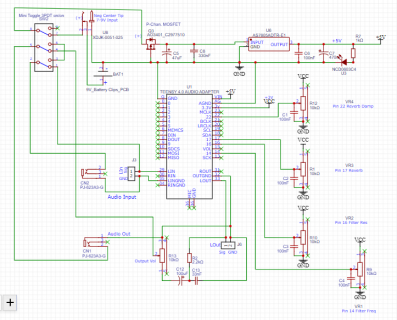
Updated the schematic with negative center power plug and 3PDT bypass switch. (I think I will just cut the trace that connects the "5V" pads to isolate the USB power from external 5V power supply.)
Could use checking of my updated schematic if anyone can would be greatly appreciated. Sincere thanks.
TonyAme
Could use checking of my updated schematic if anyone can would be greatly appreciated. Sincere thanks.
TonyAme
Attachments

BillFM
Well-known member
Connections to 3PDT switch look correct.
Since Teensy takes time to power up, audio won't be immediately heard when toggling bypass switch back-and-forth. If you're okay with this, no problem. Otherwise, a separate switch for power is needed. Keep bypass switch dedicated to audio bypass function.
It won't hurt anything by adding the 1Meg resistor. You can always remove it to see (hear) if it makes a difference. Lots of stories about how to prevent popping (most don't work).
BTW, the switched barrel power jack is available in several pin diameters. Off-hand, for guitar stomp boxes, I think it's around 2.1mm diameter, but don't quote me on that. Otherwise, match connector size with whatever you have on hand.
edit: I just looked on web for stomp box power jack: Stomp Box Power Jack
No as you don't have a coupling capacitor in the audio signal path. The resistor would discharge such a capacitor when the input is disconnected.Would using a 1M resistor here be useful for an anti-popping solution caused by a mechanical toggle switch?