High speed dual ADC - detect edges?

Status
Not open for further replies.

marin1454

Member
Hi, im trying to do a project where i will be needing a very high sampling rate. I want to use some microphones to detect loud short noises (like claps) - but i have 4 microphones(testing with 2) i want to sample with. I know the Tennsy 3.2 have 2 ADC's and im trying to understand and use Pedvide's ADC library (https://forum.pjrc.com/threads/25532-ADC-library-update-now-with-support-for-Teensy-3-1) but im not sure how to set up the high sampling rate and how to store the values for a bit?

right now i got the following code:
Code:
#include <ADC.h>

const int readPin = A3; // ADC0
const int readPin2 = A2; // ADC1

ADC *adc = new ADC(); // adc object;

void setup() {
  // put your setup code here, to run once:
Serial.begin(9600);

  Serial.println("Begin setup");
  pinMode(LED_BUILTIN, OUTPUT);
    pinMode(readPin, INPUT); //pin 23 single ended
    pinMode(readPin2, INPUT); //pin 23 single ended

adc->setSamplingSpeed(ADC_VERY_HIGH_SPEED);
adc->setConversionSpeed(ADC_VERY_HIGH_SPEED);


    adc->setAveraging(8, ADC_1); // set number of averages
    adc->setResolution(8, ADC_1); // set bits of resolution
    adc->setConversionSpeed(ADC_VERY_HIGH_SPEED, ADC_1); // change the conversion speed
    adc->setSamplingSpeed(ADC_VERY_HIGH_SPEED, ADC_1); // change the sampling speed

 // always call the compare functions after changing the resolution!
    adc->enableCompare(1.0/3.3*adc->getMaxValue(ADC_1), 0, ADC_1); // measurement will be ready if value < 1.0V
    //adc->enableCompareRange(1.0*adc->getMaxValue(ADC_1)/3.3, 2.0*adc->getMaxValue(ADC_1)/3.3, 0, 1, ADC_1); // ready if value lies out of [1.0,2.0] V
  
    
}

int value;
int value2;


void loop() {
  // put your main code here, to run repeatedly:

 value = adc->analogRead(readPin, ADC_0);
 value2 = adc->analogRead(readPin2, ADC_1);
 

}

but i have tried to add serial print to see my values and it seemse to be hard to see the diffrence in the level of sound ( seen from this code example https://github.com/pedvide/ADC/blob/master/examples/analogRead/analogRead.ino )

i know there is some background noise, but i should be able to see the claps. Right now im thinking it is because the serial print cannot keep up with the sample rate, so how can i get a fast readout of the ADC that i can see? sound quality doesnt matter, only high speed and peak readouts. also how should i store the values?


TL; DR How do i sample highspeed sound and store the data from 2 (or 4) microphones on the teensy 3.2?
 
Can you post pictures or a schematic.
What are you microphones and how are they connected? What voltages do they swing to and from. If you have an oscilloscope a picture of this in action would be good but if not a part number would suffice.

If you're only after detecting loud sounds a peak detector maybe worth considering. This is a hardware solution though and I strongly believe this can be done internal to the Teensy using your prior described ADC option
 
Well, its 4* electret microphone - i have built a circuit that gives me up to 3.3v from the microphones, and i have tested that they work on the oscilloscope, can post pictures soon.
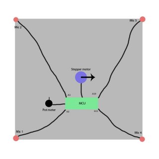
A Very simple picture of how it should work Projekt design 1.1.jpg
the output i want from the microphones i some kind of array with values, so i can identify the peaks from their value and compare the time diffrence (based on sampling rate)

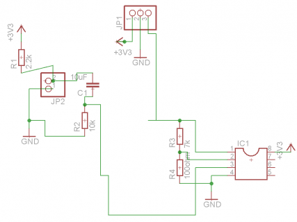
here is quick schematic from the microphone schematics where jp2 is the microphone and ic1 is a op-amp mic.PNG
 
Last edited:
That's for the comprehensive images!

Have you tried using the built in ADC library: analogRead(pin);?
 
Yeah, but Im not sure if it will sample fast enough for me - i need to sample enough to read values at a good bit faster than 1.47058824 milliseconds - the faster the better - my project is all about the delay in sound between the 4 microphones
 
Yeah, but Im not sure if it will sample fast enough for me - i need to sample enough to read values at a good bit faster than 1.47058824 milliseconds - the faster the better - my project is all about the delay in sound between the 4 microphones

if you really wanted to go fast, you must use DMA, especially if you wanted to estimate time delays between microphones.
What is the distance between microphones?
 
Yeah, but Im not sure if it will sample fast enough for me - i need to sample enough to read values at a good bit faster than 1.47058824 milliseconds - the faster the better - my project is all about the delay in sound between the 4 microphones

gunshot direction detectors use low microseconds per sample. Speed of sound at sea level nominal is 768mph (340 m/h). Divide that out to get ft/sec or m/sec
 
Last edited:
Yeah, but Im not sure if it will sample fast enough for me
Give it a try and see if it works anyways. We need to rule out that this isn't a hardware issue. Then we'll get the library working

if you really wanted to go fast, you must use DMA
I'm not sure DMA will help. It'll retrieve the data faster, sure. But it still has to be processed in realtime... Actually WMXZ do you want this done in realtime?

Some back of the envelope calculations here:
If a perfect read speed of 3.75us is achieved and
the speed of sound in air is 343m/s, it'll cover 1.2mm in one read.
This gives you quite a bit of wiggle room depending on how accurate you want it
 
Last edited:
if you really wanted to go fast, you must use DMA, especially if you wanted to estimate time delays between microphones.
What is the distance between microphones?

it is precisely what i want to measure - my distance is 0.5m between the microphones - Do you have any introduction to DMA? have no idea what it is?
 
Give it a try and see if it works anyways. We need to rule out that this isn't a hardware issue. Then we'll get the library working


I'm not sure DMA will help. It'll retrieve the data faster, sure. But it still has to be processed in realtime

Real time processing is not a problem - want it to run a trigger (a threshold) and if the soundlevel passes the threshold, it will sample for a short periode of time and then it will pause the sampling and calculate the stuff i need
 
Hi, im trying to do a project where i will be needing a very high sampling rate. I want to use some microphones to detect loud short noises (like claps) - but i have 4 microphones(testing with 2) i want to sample with. I know the Tennsy 3.2 have 2 ADC's and im trying to understand and use Pedvide's ADC library (https://forum.pjrc.com/threads/25532-ADC-library-update-now-with-support-for-Teensy-3-1) but im not sure how to set up the high sampling rate and how to store the values for a bit?

right now i got the following code:
Code:
#include <ADC.h>

const int readPin = A3; // ADC0
const int readPin2 = A2; // ADC1

ADC *adc = new ADC(); // adc object;

void setup() {
  // put your setup code here, to run once:
Serial.begin(9600);

  Serial.println("Begin setup");
  pinMode(LED_BUILTIN, OUTPUT);
    pinMode(readPin, INPUT); //pin 23 single ended
    pinMode(readPin2, INPUT); //pin 23 single ended

adc->setSamplingSpeed(ADC_VERY_HIGH_SPEED);
adc->setConversionSpeed(ADC_VERY_HIGH_SPEED);


    adc->setAveraging(8, ADC_1); // set number of averages
    adc->setResolution(8, ADC_1); // set bits of resolution
    adc->setConversionSpeed(ADC_VERY_HIGH_SPEED, ADC_1); // change the conversion speed
    adc->setSamplingSpeed(ADC_VERY_HIGH_SPEED, ADC_1); // change the sampling speed

 // always call the compare functions after changing the resolution!
    adc->enableCompare(1.0/3.3*adc->getMaxValue(ADC_1), 0, ADC_1); // measurement will be ready if value < 1.0V
    //adc->enableCompareRange(1.0*adc->getMaxValue(ADC_1)/3.3, 2.0*adc->getMaxValue(ADC_1)/3.3, 0, 1, ADC_1); // ready if value lies out of [1.0,2.0] V
  
    
}

int value;
int value2;


void loop() {
  // put your main code here, to run repeatedly:

 value = adc->analogRead(readPin, ADC_0);
 value2 = adc->analogRead(readPin2, ADC_1);
 

}

but i have tried to add serial print to see my values and it seemse to be hard to see the diffrence in the level of sound ( seen from this code example https://github.com/pedvide/ADC/blob/master/examples/analogRead/analogRead.ino )

i know there is some background noise, but i should be able to see the claps. Right now im thinking it is because the serial print cannot keep up with the sample rate, so how can i get a fast readout of the ADC that i can see? sound quality doesnt matter, only high speed and peak readouts. also how should i store the values?


TL; DR How do i sample highspeed sound and store the data from 2 (or 4) microphones on the teensy 3.2?

Your missing some code in your loop from the looks of it. In your loop your asking for the Value but you never told it to do a read.

Im at work so I cant really do to much, here is an ADC test code I made for my Gocart project. You can see the "result = adc->analogSynchronizedRead" that needs to be called. Without that its just reading the initialized value that the value and value2 where set to during startup.

Code:
#include <ADC.h>

const int aThrottle = A10;    //Throttle
const int aCurrent = A18;  //Current
const int aBusV = A11;   //BusV
const int aBattV = A19;  //BattV
const int aMotorT = A12;   //MotorTemp
const int aHST = A20;  //HS-Temp


ADC *adc = new ADC(); // adc object


void setup() {

    pinMode(LED_BUILTIN, OUTPUT);
    pinMode(aThrottle, INPUT);
    pinMode(aCurrent, INPUT);
    pinMode(aBusV, INPUT);
    pinMode(aBattV, INPUT);
    pinMode(aMotorT, INPUT);
    pinMode(aHST, INPUT);


    Serial.begin(9600);

    ///// ADC0 ////
    //adc->setReference(ADC_REF_INTERNAL, ADC_0); change all 3.3 to 1.2 if you change the reference

    adc->setAveraging(1); // set number of averages
    adc->setResolution(12); // set bits of resolution

    // it can be ADC_VERY_LOW_SPEED, ADC_LOW_SPEED, ADC_MED_SPEED, ADC_HIGH_SPEED_16BITS, ADC_HIGH_SPEED or ADC_VERY_HIGH_SPEED
    // see the documentation for more information
    adc->setConversionSpeed(ADC_HIGH_SPEED); // change the conversion speed
    // it can be ADC_VERY_LOW_SPEED, ADC_LOW_SPEED, ADC_MED_SPEED, ADC_HIGH_SPEED or ADC_VERY_HIGH_SPEED
    adc->setSamplingSpeed(ADC_HIGH_SPEED); // change the sampling speed

    ////// ADC1 /////
    adc->setAveraging(1, ADC_1); // set number of averages
    adc->setResolution(12, ADC_1); // set bits of resolution
    adc->setConversionSpeed(ADC_HIGH_SPEED, ADC_1); // change the conversion speed
    adc->setSamplingSpeed(ADC_HIGH_SPEED, ADC_1); // change the sampling speed


    delay(500);
    Serial.println("end setup");
}

int value[16] = {0};
int value2[16] = {0};
int value3[16] = {0};
int value4[16] = {0};
int value5[16] = {0};
int value6[16] = {0};
int testtime;

ADC::Sync_result result;

void loop() {
  
int i;

elapsedMicros sinceStart; // start the clock

for (i = 0; i < 16; i++) {
    result = adc->analogSynchronizedRead(aThrottle, aCurrent);
    value[i] = result.result_adc0;
    value2[i] = result.result_adc1;
    result = adc->analogSynchronizedRead(aBusV, aBattV);
    value3[i] = result.result_adc0;
    value4[i] = result.result_adc1;
    result = adc->analogSynchronizedRead(aMotorT, aHST);
    value5[i] = result.result_adc0;
    value6[i] = result.result_adc1;

}

testtime = sinceStart;   //how long it took to read all 6 pins 16 times.
Serial.print("Full read time was ");
Serial.print(testtime);
Serial.println(" us");

//First ADC array                        
    Serial.print("Pin: ");   //Copy and paste hell from here on out...
    Serial.print(aThrottle);
    Serial.print(", value ADC0: ");

for (i = 0; i < 16; i++) {
    Serial.print(value[i]*3.27/adc->getMaxValue(ADC_0), DEC);   //using 3.27 as the true voltage value
        Serial.print(" ");  
}

//Second ADC array
    Serial.println(" ");
    Serial.print("Pin: ");   //Copy and paste hell from here on out...
    Serial.print(aCurrent);
    Serial.print(", value ADC1: ");

for (i = 0; i < 16; i++) {
    Serial.print(value2[i]*3.27/adc->getMaxValue(ADC_1), DEC);  
        Serial.print(" ");
}

//Third ADC array
    Serial.println(" ");
    Serial.print("Pin: ");   //Copy and paste hell from here on out...
    Serial.print(aBusV);
    Serial.print(", value ADC0: ");

for (i = 0; i < 16; i++) {
    Serial.print(value3[i]*3.27/adc->getMaxValue(ADC_0), DEC);
        Serial.print(" ");  
}

//Forth ADC array
    Serial.println(" ");
    Serial.print("Pin: ");   //Copy and paste hell from here on out...
    Serial.print(aBattV);
    Serial.print(", value ADC1: ");

for (i = 0; i < 16; i++) {
    Serial.print(value4[i]*3.27/adc->getMaxValue(ADC_1), DEC);
      Serial.print(" ");  
}

//Fifth ADC array
    Serial.println(" ");
    Serial.print("Pin: ");   //Copy and paste hell from here on out...
    Serial.print(aMotorT);
    Serial.print(", value ADC0: ");

for (i = 0; i < 16; i++) {
    Serial.print(value5[i]*3.27/adc->getMaxValue(ADC_0), DEC);
      Serial.print(" ");  
}

//Sixth ADC array
    Serial.println(" ");
    Serial.print("Pin: ");   //Copy and paste hell from here on out...
    Serial.print(aHST);
    Serial.print(", value ADC1: ");

for (i = 0; i < 16; i++) {
    Serial.print(value6[i]*3.27/adc->getMaxValue(ADC_1), DEC);
      Serial.print(" ");  
}

Serial.println(" ");
  delay(1000);
}

edit...
IIRC I was getting about 4.5-5uS per read with the above code.
 
Last edited:
it is precisely what i want to measure - my distance is 0.5m between the microphones - Do you have any introduction to DMA? have no idea what it is?

OK, 0.5 m means in air you need a buffer of 2 ms (at least for diagonal distance). I would add some extra delay to be sure you catch all events in a single block. Now, if you wanted to use 256 point radix 4 FFT for cross-correlation, you need to sample your data with 256 kHz, which is very high indeed, but feasible, but only with Direct Memory Access (DMA), where ADC writes directly into memory and launches an interrupt when finished.

Real time processing is not a problem - want it to run a trigger (a threshold) and if the soundlevel passes the threshold, it will sample for a short periode of time and then it will pause the sampling and calculate the stuff i need

Yes, in the interrupt service routine, you can check first the max level, and do cross-correlation only on demand.

This is what would I do for direction finding.
 
Why not take 4 pins of the FTM0 in input capture mode, and drive these from simple comparators/schmitt triggers between the microphones and the pins? This will allow to resolve time differences with a resolution of 20.83ns (assuming F_BUS is set to 48Mhz) which theoretically allows measuring distances down to about 7um if the sound speed is 334m/s. Example code on how to use the FTM0 in input capture mode can be found for example in the FreqMeasureMulti library which would naturally have to be adapted for that purpose. But very easy and without ADCs and FFT...
 
OK, 0.5 m means in air you need a buffer of 2 ms (at least for diagonal distance). I would add some extra delay to be sure you catch all events in a single block. Now, if you wanted to use 256 point radix 4 FFT for cross-correlation, you need to sample your data with 256 kHz, which is very high indeed, but feasible, but only with Direct Memory Access (DMA), where ADC writes directly into memory and launches an interrupt when finished.


Yes, in the interrupt service routine, you can check first the max level, and do cross-correlation only on demand.

This is what would I do for direction finding.
Any exampels on DMA? have never seen or heard about it, but sounds like a solution if i can get it to work.

Why not take 4 pins of the FTM0 in input capture mode, and drive these from simple comparators/schmitt triggers between the microphones and the pins? This will allow to resolve time differences with a resolution of 20.83ns (assuming F_BUS is set to 48Mhz) which theoretically allows measuring distances down to about 7um if the sound speed is 334m/s. Example code on how to use the FTM0 in input capture mode can be found for example in the FreqMeasureMulti library which would naturally have to be adapted for that purpose. But very easy and without ADCs and FFT...
so let me get this straight: 1: take the microphones and couple up to some schmitt trigger to convert the signal to 5v when it is over a threshold - then use the FTM0 pins to measure the time diffrence ?

- To you all - thanks for all the help :)
 
Why not take 4 pins of the FTM0 in input capture mode, and drive these from simple comparators/schmitt triggers between the microphones and the pins? This will allow to resolve time differences with a resolution of 20.83ns (assuming F_BUS is set to 48Mhz) which theoretically allows measuring distances down to about 7um if the sound speed is 334m/s. Example code on how to use the FTM0 in input capture mode can be found for example in the FreqMeasureMulti library which would naturally have to be adapted for that purpose. But very easy and without ADCs and FFT...

Sure,
If you have a hardware solution, why doing it in software.

If the gun-shot is close by (high SNR 60+dB) then no problem, if distant shots (15 to 20 dB SNR) then hardware (threshold setting) becomes a little bit more trickier.
 
As I said, look at the code of the FreqMeasureMulti library and at the K20 reference manual. The FTMs have their own timers and input capture mechanisms, so that there is no need to fiddle with pin interrupts. They work independently from other hardware resources as autonomous subsystems which makes them highly precise, even if the CPU is under heavy load. PWM is one possible application for that, Input capture another. Out of that, these Flex timer modules (FTM) offer still more functionalities, i.e. quadrature decoding. Most of them can be configured individually for each pin or for a pair of pins. So, for example, you might capture pulse events on some pins while outputting PWM at others, as long as the common clock selector, pre scaler, and modulus value are not altered.

For input capture, the timer value of the last raising or falling event at each pin is saved in a dedicated register, then a common interrupt is raised which allows to carry about rollover, saving the current register of the pin which saw an event to a buffer, clear the interrupt flag for the next event, and so on. All pin capture registers can then be read asynchronously in one run and you'll only have to calculate the time difference by simple subtraction.
 
Last edited:
As I said, look at the code of the FreqMeasureMulti library and at the K20 reference manual. The FTMs have their own timers and input capture mechanisms, so that there is no need to fiddle with pin interrupts. They work independently from other hardware resources as autonomous subsystems which makes them highly precise, even if the CPU is under heavy load. PWM is one possible application for that, Input capture another. Out of that, these Flex timer modules (FTM) offer still more functionalities, i.e. quadrature decoding. Most of them can be configured individually for each pin or for a pair of pins. So, for example, you might capture pulse events on some pins while outputting PWM at others, as long as the common clock selector, pre scaler, and modulus value are not altered.

For input capture, the timer value of the last raising or falling event at each pin is saved in a dedicated register, then a common interrupt is raised which allows to carry about rollover, saving the current register of the pin which saw an event to a buffer, clear the interrupt flag for the next event, and so on. All pin capture registers can then be read asynchronously in one run and you'll only have to calculate the time difference by simple subtraction.

All right - sounds like a good way to work with it - will look into it the first thing in the morning - Thanks :D
 
The concept is the 16 bit timer is configured to always rapidly increment. The channels are configured for "input capture", which means the rapidly changing number is instantly captured to the channel value register when the pin sees a rising edge.

You do not necessarily need interrupts to read the registers. Interrupts always make everything harder to develop. If you're not experienced with this sort of programming, I recommend avoiding interrupts. (and even if you are experienced, why make things harder?)

FreqMeasureMulti uses interrupts because the edges repeat very rapidly on each channel. It's published as a library meant to work with a wide range of projects, where you might have all sorts of other code. Interrupts allow it to (usually) work regardless of other code.

For this application, where it's a single event, I'd suggest avoiding interrupts. Or avoid them at first, until you get it working without them. Interrupts always make developing and testing much, much harder.

In this case, you can just write some code that sets up two channels with input capture mode. Then just repeatedly check both the channel flags to detect when both have captured edges. Read the 2 captured values, and subtract. Easy, right? If you're able to read the 2 numbers, subtract, and get the info transmitted or stored quickly enough to get back to listening again, then problem solved.

Don't make it a lot harder than it needs to be with interrupts! Or if you do, at least do your sanity a favor and get it working the simplest way first. Save your work! Fiddling with interrupts is not easy. You really do not need interrupts unless the pulses repeat very rapidly, or if your code will be doing other work instead of listening for the input captures to happen. General purpose libraries are written with interrupts so they can work for those types of cases. For a project where you can know your code is checking the input captures, you don't need to go to the trouble of interrupts.

so let get this straight - the timer's / channels is default configured for input capture -

you say i should avoid interrupts, so

I have 4 microphones that i have passed through 4 comparator so they will emit a 3.3v pulse when sound is detected.
Now i will need to measure the diffrence - since i have 4 microphones that i want to measure - should i use some specific Pins on the board to spread out the microphones?
also to count the diffrence, how will i do that? i found this: https://github.com/cTn-dev/Phoenix-...ibraries/P_Receiver/Receiver_teensy3_HW_PPM.h
but it seems like it is only for 1 pin and not 4 like mine.

do you have any code example for setting the 4 channels up and how to "read" the value?

Update - when searching for diffrent solution i found "digitalreadfast" and it seemse like it could be fast enough - so might just end up using digital read fast and using micros() to measure time
 
Last edited:
Status
Not open for further replies.
Back
Top