Modbus RTU

Hello,
I actually I want to Communicate my Teensy 4.1 with Modbus RS485 using MAX 485 Chip. I want this System to work as a Slave in my master network on MODBUS RS485/RTU.

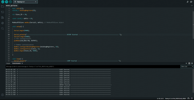
So can any one help me with it like this is the code I am burning on my teensy device.

Code:
#include <ModbusRTUSlave.h>

// Modbus Configuration
bool coils[1];
uint16_t holdingRegisters[9];

int Slave_ID = 10;

const uint8_t dePin = 19;    

ModbusRTUSlave modbus(Serial5, dePin); // ModbusRTUSlave object

void setup() {

  Serial.begin(9600);
  Serial.println("-------------------------------------------------SETUP Started ------------------------------------------------- ");
  Serial5.begin(9600);
  // Pin configurations
  pinMode(LED_BUILTIN, OUTPUT);

  // Modbus initialization
  modbus.configureHoldingRegisters(holdingRegisters, 14);
  modbus.configureCoils(coils, 1);
  modbus.begin(Slave_ID, 9600);

}

void loop() {
  Serial.println("-------------------------------------------------LOOP Started ------------------------------------------------- ");
  modbus.poll(); // Poll Modbus communication

    // Control LED based on coil value
    digitalWrite(LED_BUILTIN, coils[0] ? LOW : HIGH);

    // Update holding registers
    holdingRegisters[0] = 7;
    holdingRegisters[1] = 12;
    holdingRegisters[2] = 8;
    holdingRegisters[3] = 85;
    holdingRegisters[4] = 60;
    holdingRegisters[5] = 25;
    holdingRegisters[6] = 45;
    holdingRegisters[7] = 50;
    holdingRegisters[8] = 80;

  delay(1000);
  Serial.flush();
}
 

Attachments

  • 1713022111475.png
    1713022111475.png
    101.7 KB · Views: 65
Like I said, you need to change some AVR registers to equivalent Teensy counterparts. Look for void Modbus::begin at line #254 and replace it by this:

Code:
void Modbus::begin(long u32speed) {

  switch( u8serno ) {
  case 1:
    port = &Serial1;
    port->begin(u32speed);
    break;
  case 2:
    port = &Serial2;
    port->begin(u32speed);
    break;
  case 3:
    port = &Serial3;
    port->begin(u32speed);
    break;
  case 0:
  default:
    port = &Serial1;
    break;
  }
  //port->begin(u32speed);

  if (u8txenpin > 1) { // pin 0 & pin 1 are reserved for RX/TX
    // return RS485 transceiver to transmit mode
    pinMode(u8txenpin, OUTPUT);
    digitalWrite(u8txenpin, LOW);
  }

  port->flush();
  u8lastRec = u8BufferSize = 0;
  u16InCnt = u16OutCnt = u16errCnt = 0;
}

And the same a bit lower for
Code:
void Modbus::begin(long u32speed,uint8_t u8config) {

  switch( u8serno ) {
  case 1:
    port = &Serial1;
    port->begin(u32speed, u8config);
    break;
  case 2:
    port = &Serial2;
    port->begin(u32speed, u8config);
    break;
  case 3:
    port = &Serial2;
    port->begin(u32speed, u8config);
    break;
  case 0:
  default:
    port = &Serial1;
    break;
  }

  //port->begin(u32speed, u8config);
  if (u8txenpin > 1) { // pin 0 & pin 1 are reserved for RX/TX
    // return RS485 transceiver to transmit mode
    pinMode(u8txenpin, OUTPUT);
    digitalWrite(u8txenpin, LOW);
  }

  port->flush();
  u8lastRec = u8BufferSize = 0;
  u16InCnt = u16OutCnt = u16errCnt = 0;
}

I was planning to write some examples on my blog, but haven't got around to it.
Hi all,

Its very simple to get this working with a Teensy I used a Grove module Grove-RS485 see link,

https://www.kiwi-electronics.com/nl...MI36755tO_hQMV_rCDBx0DWw2REAQYASABEgIL-PD_BwE

Best regards,
Johan

Code:
// Modbus RS485
// J.G. Holstein @ 2023

#include <SensorModbusMaster.h>
// Define the sensor's ID modbus address
modbusMaster modbus1;
//modbusMaster modbus2;
//modbusMaster modbus3;

unsigned long poll = 100;
unsigned long previousMillis = 0;

// Set ID's for modbus device
byte modbusAddress1 = 1;    // SlaveID 1
//byte modbusAddress2 = 2;  // SlaveID 2
//byte modbusAddress3 = 3;  // SlaveID 3

float M1Measure;
String M1CapacityUnit = " ";

void setup() {
  Serial.begin(115200);             // Main serial port for debugging via USB Serial Monitor
  Serial5.begin(19200, SERIAL_8E1);  // Teensy 4.0 port for communicating with modbus device

  modbus1.begin(modbusAddress1, &Serial5);    // Device ID1
  //modbus2.begin(modbusAddress2, &Serial5);  // Device ID2
  //modbus3.begin(modbusAddress3, &Serial5);  // Device ID3

}

void loop() {

  unsigned long currentMillis = millis();

  if (currentMillis - previousMillis >= poll)
  {
    M1Measure = modbus1.float32FromRegister(0x03, 41216, bigEndian);
    if (modbus1.getRegisters(0x03, 0x81F8, 5)) {
      M1CapacityUnit = modbus1.StringFromFrame(7);
    }
    Serial.print("Measure M1 : ");
    Serial.print(M1Measure);
    Serial.print(",");
    Serial.print("M1CapacityUnit M1: ");
    Serial.print(M1CapacityUnit);
    Serial.print(",");
    previousMillis = currentMillis;
  }
}

Bro thanks for your advice but actually I want to do it using a MAX485 8 pin chip So it is is their any way to do it.
I have connected the MAX485 with this respective pin of teensy 4.1
DE and RE Pin = 19;
RO Pin = 21;
DE Pin = 20;
that is Serial5 of Teensy.

So is their any issues with the logic levels since Teensy communicate on 3.3V and MAX485 on 5V.
I am stuck at this also if I try to go ur way then also it will take to much time for the Module you suggested to import here in INDIA
 
The Teensy 3.3V output will be able to drive the MAX485 but the MAX495 output voltage(to the Teensy) at 5V will be too high and will probably damage the Teensy.
If not immediately then will lead to future degradation and damage.
You will need a step down converter from the MAX485 to the Teensy.
You could use something like ADUM1201 for level conversion.

How about this MOSFET operated Bidirectional logic level converter ckt from this website mention below. Will it work? What if i use this between teensy 4.1 and MAX 485 Chip. Actually I am trying it now.
1713120645126.png


https://electrocredible.com/logic-l...ic_Level_Converter_Circuit_using_a_Transistor
 
The Teensy 3.3V output will be able to drive the MAX485 but the MAX495 output voltage(to the Teensy) at 5V will be too high and will probably damage the Teensy.
If not immediately then will lead to future degradation and damage.
You will need a step down converter from the MAX485 to the Teensy.
You could use something like ADUM1201 for level conversion.
Or use one of the many MAXIM 3.3V RS485 chips.
 
That circuit should work fine for normal baud rates.
this Level Shifter CKT works fine with the I2C pin but I am not receiving any output when Connected with MAX485 Chip Ckt on the master end . So do am I using the wrong Modbus lib for Teensy ??
Slave Code : (Teensy side )

Code:
#include <ModbusRTUSlave.h>

// Modbus Configuration
bool coils[1];
uint16_t holdingRegisters[9];

int Slave_ID = 10;

const uint8_t dePin = 22;   

ModbusRTUSlave modbus(Serial5, dePin); // ModbusRTUSlave object

void setup() {

  Serial.begin(9600);
  Serial.println("-------------------------------------------------SETUP Started ------------------------------------------------- ");
  Serial5.begin(38400);
  // Pin configurations
  pinMode(LED_BUILTIN, OUTPUT);

  // Modbus initialization
  modbus.configureHoldingRegisters(holdingRegisters, 14);
  modbus.configureCoils(coils, 1);
  modbus.begin(Slave_ID, 38400);

}

void loop() {
  Serial.println("-------------------------------------------------LOOP Started ------------------------------------------------- ");
  modbus.poll(); // Poll Modbus communication

    // Control LED based on coil value
    digitalWrite(LED_BUILTIN, coils[0] ? HIGH : LOW );

    // Update holding registers
    holdingRegisters[0] = 7;
    holdingRegisters[1] = 12;
    holdingRegisters[2] = 8;
    holdingRegisters[3] = 85;
    holdingRegisters[4] = 60;
    holdingRegisters[5] = 25;
    holdingRegisters[6] = 45;
    holdingRegisters[7] = 50;
    holdingRegisters[8] = 80;

  delay(1000);
  Serial.flush();
}

Master Code : (Python code Running on my PC )
Code:
from pymodbus.client import ModbusSerialClient

# Define the Modbus slave ID
slave_id = 10

# Define the Modbus serial port parameters
port = 'COM7'  # Change this to your serial port
baudrate = 38400
timeout = 1

# Connect to the Modbus RTU slave
client = ModbusSerialClient(method='rtu', port=port, baudrate=baudrate, timeout=timeout)
client.connect()

if client.is_socket_open():
    # Read holding registers from the Modbus RTU slave
    start_register = 0  # Starting address of the holding registers
    num_registers = 9   # Number of holding registers to read

    # Modbus function code 0x03 is used to read holding registers
    response = client.read_holding_registers(start_register, num_registers, unit=slave_id)

    if response.isError():
        print("Error: {}".format(response))
    else:
        # Print the holding register values
        print("Holding Registers:")
        for i, value in enumerate(response.registers):
            print("Register {}: {}".format(i, value))
else:
    print("Failed to connect to Modbus RTU slave.")

# Close the Modbus connection
client.close()
 
Or use one of the many MAXIM 3.3V RS485 chips.
I have a RPI RS485 CAN Hat Module so Should I use its Chip but I have doubt the the MAX3485 Chip runs on 3.3V right but the A and B Pins Side is working on 5V so does it not damage the MAX3485 Chip. Is their any reference doc you can share the to build MAX3485 CKT.
 
Is their any reference doc you can share the to build MAX3485 CKT.
For documents, use Google or other search engine.

I think you are confusing the signal requirements on the RS485 side and the micro-controller side. The RS485 side can handle voltages in excess of Vcc. See data sheet. (Common mode range: -7V to 12V)

And read The Art and Science of RS485 from Circuit Cellar Ink, 1999. Google can find copies.
 
Back
Top