MODBUS TCP

Lavanya rajan

Well-known member
Dear Team,

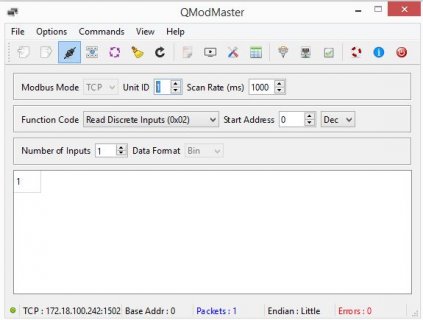
I'm trying to read Digital input status from IO Module that transmits data using MODBUS TCP/IP protocol. I used Qmodmaster software to read the data and its working fine. Screenshot attached for the same.
Now I'm trying to read the same digital input using Teensy 4.0 controller along with w5500 (https://protosupplies.com/product/ethernet-module-w5500/)Ethernet module. I understand that Modbus TCP/IP uses port 502 but this module required port no of 1502.

I used this code, but the output is always 1 though digital input status changes. Can any body help me on this
Code:
#include <SPI.h>
#include <Ethernet.h>
#include <Modbus.h>
#include <ModbusIP.h>

ModbusIP mb;
const int switchPin = 0;  // Change this to the actual pin you have connected the switch to
const int SWITCH_ISTS = 0;
const int PORT     = 1502;
const int SLAVE_ID = 1;

void setup() {
  Serial.begin(9600);
  Ethernet.init(29);
 
  byte mac[] = { 0x00, 0x60, 0xE9, 0x2A, 0x4E, 0x4C };
  byte ip[] = { 172, 18, 100, 242 };  // Change this to your Arduino's IP address

  Ethernet.begin(mac, ip);

   if (Ethernet.hardwareStatus() == EthernetNoHardware) {
    Serial.println("Ethernet module was not found - Stopping Test");
    while (true) {
      delay(1); // do nothing, no point running without Ethernet hardware
    }
  }
  mb.config(mac, ip);
  mb.addIsts(SWITCH_ISTS);

}

void loop() {
  mb.task();
  mb.Ists(SWITCH_ISTS, digitalRead(switchPin));
  Displayvalue();
  delay(1000);
}

void Displayvalue() {
  String Printstr = "Switch state is: " + String(mb.Ists(SWITCH_ISTS));
  Serial.println(Printstr);
}
 

Attachments

  • modbus tcp.JPG
    modbus tcp.JPG
    43.2 KB · Views: 41
I'm not familiar with Modbus so I may not be very helpful but my first question is: which exact library are you using?
This one perhaps? I see an example sketch that looks similar to your code above:
C++:
/*
  Modbus-Arduino Example - Switch (Modbus IP)
  Copyright by André Sarmento Barbosa
  http://github.com/andresarmento/modbus-arduino
*/
 
#include <SPI.h>
#include <Ethernet.h>
#include <Modbus.h>
#include <ModbusIP.h>

//Modbus Registers Offsets (0-9999)
const int SWITCH_ISTS = 100;
//Used Pins
const int switchPin = 3;

//ModbusIP object
ModbusIP mb;

void setup() {
    // The media access control (ethernet hardware) address for the shield
    byte mac[] = { 0xDE, 0xAD, 0xBE, 0xEF, 0xFE, 0xED }; 
    // The IP address for the shield
    byte ip[] = { 192, 168, 1, 120 };   
    //Config Modbus IP
    mb.config(mac, ip);
    //Set ledPin mode
    pinMode(switchPin, INPUT);
    // Add SWITCH_ISTS register - Use addIsts() for digital inputs
    mb.addIsts(SWITCH_ISTS);
}

void loop() {
   //Call once inside loop() - all magic here
   mb.task();
  
   //Attach switchPin to SWITCH_ISTS register     
   mb.Ists(SWITCH_ISTS, digitalRead(switchPin));
}

Paul
 
Hi Paul,

Thanks for your reply.
I used same library and example code. modified it just to read the status of digital input of tcp device
 
modified little more bit
Code:
#include <SPI.h>
#include <Ethernet.h>
#include <Modbus.h>
#include <ModbusIP.h>

byte ethMac[] = { 0xDE, 0xAD, 0xBE, 0xEF, 0xFE, 0xED }; // Replace with your Ethernet shield's MAC address
IPAddress ethFixedIp(172, 18, 100, 250);  // Set your Ethernet shield's desired fixed IP address

byte modbusMac[] = { 0x00, 0x60, 0xE9, 0x2A, 0x4E, 0x4C }; // Replace with your Modbus device's MAC address
IPAddress modbusIp(172, 18, 100, 242);  // Set your Modbus device's IP address

EthernetClient client;
ModbusIP mb;
const int SWITCH_ISTS = 100001; // Replace with your specific Modbus address

void setup() {
  Ethernet.init(29); // Most Arduino shields

  Serial.begin(9600);
  while (!Serial) {
    ; // Wait for the serial port to connect
  }

  Serial.println("Initialize Ethernet with fixed IP:");
  Ethernet.begin(ethMac, ethFixedIp);

  Serial.print("  Fixed IP address: ");
  Serial.println(ethFixedIp);
  // Print MAC address
  Serial.print("  MAC address: ");
  uint8_t macAddress[6];
  Ethernet.MACAddress(macAddress);
  for (int i = 0; i < 6; i++) {
    Serial.print(macAddress[i], HEX);
    if (i < 5) Serial.print(":");
  }
  Serial.println();


  // Modbus configuration
  mb.config(modbusMac, modbusIp);
  mb.addIsts(SWITCH_ISTS);
}

void loop() {
  mb.task();

  int switchState = mb.Ists(SWITCH_ISTS);
  Displayvalue(switchState);

  // Your Modbus communication code goes here using Modbus.h library

  delay(1000);
}

void Displayvalue(int switchState) {
  String Printstr = "Discrete Input state is: " + String(switchState);
  Serial.println(Printstr);
}
 
From the library README, the "lsts" function needs two parameters:
mb.Ists (SWITCH_ISTS, digitalRead (switchPin));.
Does that matter? It's also shown in the example.

Paul
 
Just to be sure that I understand your application (and Modbus) correctly: the Teensy 4.0 will be a Modbus slave? And you want to read out a digital pin on the Teensy by using e.g. Qmodmaster?

Paul
 
Actually I have modbus TCP based device which has digital inputs and digital outputs, I connected a proximity sensor output to digital input of this device and I'm reading the status of this pin using Qmodmaster software.

Now same thing I need to replicate using teensy 4.0 and W5500 Ethernet module. I just want to read the status of tcp device's digital input. I'm not sure why digital pin is required for "the "lsts" function needs two parameters:
mb.Ists (SWITCH_ISTS, digitalRead (switchPin));."
 
I just want to read the status of tcp device's digital input.
By "tcp device's digital input" I assume you mean the Teensy 4.0?
I'm not sure why digital pin is required for "the "lsts" function needs two parameters:
mb.Ists (SWITCH_ISTS, digitalRead (switchPin));."
Well, I can imagine that you have to tell the library which digital pin on the Teensy you want to expose to the Modbus.

Paul
 
By "tcp device's digital input" I assume you mean the Teensy 4.0?

Well, I can imagine that you have to tell the library which digital pin on the Teensy you want to expose to the Modbus.

Paul
I'm not understanding why digital pin has to be exposed to the modbus, why cannot I directly print it on serial monitor
 
now modified code but still not getting the output properly.
Code:
/*
  Modbus-Arduino Example - Switch (Modbus IP)
  Copyright by André Sarmento Barbosa
  http://github.com/andresarmento/modbus-arduino
*/
 
#include <SPI.h>
#include <Ethernet.h>
#include <Modbus.h>
#include <ModbusIP.h>

//Modbus Registers Offsets (0-9999)
const int SWITCH_ISTS = 100;
//Used Pins
const int switchPin = 3;
int j;
//ModbusIP object
ModbusIP mb;
EthernetClient client;
void setup() {
  Ethernet.init(29); // Most Arduino shields
    // The media access control (ethernet hardware) address for the shield
    byte mac[] = { 0xDE, 0xAD, 0xBE, 0xEF, 0xFE, 0xED };
    // The IP address for the shield
    byte ip[] = { 172, 18, 7, 161 };   
    //Config Modbus IP
    while (!Serial) {
    ; // Wait for the serial port to connect
  }

  Serial.println("Initialize Ethernet with fixed IP:");
  Ethernet.begin(mac, ip);

  Serial.print("  Fixed IP address: ");
  Serial.println(ip[j]);
  // Print MAC address
  Serial.print("  MAC address: ");
  uint8_t macAddress[6];
  Ethernet.MACAddress(macAddress);
  for (int i = 0; i < 6; i++) {
    Serial.print(macAddress[i], HEX);
    if (i < 5) Serial.print(":");
  }
  Serial.println();
    mb.config(mac, ip);
    //Set ledPin mode
    pinMode(switchPin, INPUT);
    // Add SWITCH_ISTS register - Use addIsts() for digital inputs
    mb.addIsts(SWITCH_ISTS);
}

void loop() {
   //Call once inside loop() - all magic here
   mb.task();
 
   //Attach switchPin to SWITCH_ISTS register     
   mb.Ists(SWITCH_ISTS, digitalRead(switchPin));
    Displayvalue();
 
  delay(1000);
}

void Displayvalue() {
  int switchState = mb.Ists(SWITCH_ISTS);
  String Printstr = "Switch state is: " + String(switchState);
  Serial.println(Printstr);
}

modbus setting of the device is attached
 

Attachments

  • modbus settings.JPG
    modbus settings.JPG
    114.7 KB · Views: 20
I'm lost... :unsure:
This library is for a Modbus slave, so the Teensy is going to be a slave. In the current version the library allows the Arduino operate as a slave, supporting Modbus Serial and Modbus over IP.
A Modbus master is able to read out input & output pins of a slave (the Teensy). And thus you have to tell the library which pins to expose on the Modbus.
Would it be possible for you to answer the questions I raised in my previous posts? Then I will be able to understand your application and be perhaps be able to answer your questions.

Thanks,
Paul
 
Last edited:
I will tell you what I understood, please correct me if I have been understood it wrongly.

So, I'm trying to establish Modbus TCP communication through ethernet with Atop IoT module as slave and Teensy 4.0 ctlr with Ethernet shield(W5500) as master. With Modbus slave simulating program on PC (i.e Qmodmaster software) it works fine and I'm able to read Discrete input values of Atop module as I attached my previous screenshot.

But Teensy is not able to establish the communication with Atop module and fetch its discrete Input values.
 
Allright, thanks. It's clear now what you want to accomplish.
From what I read and viewed on the internet [here, here, here and here], the master requests a transfer and the slave responds.
If you want the Teensy to act as a master, you need a different library than the one I referred to initially.
Perhaps this one or this one is usable. Mind you: in Modbus speak, a Client equals a Master, a Server equals a Slave.

Paul

PS: Qmodmaster is a Master-simulating program
 
Thanks paul for enlightening me, May be I might have confused with client server method in Modbus TCP. I'll check upon the one libraries you mentioned and come back to you
 
Back here,

Perhaps this one or this one is usable. Mind you: in Modbus speak, a Client equals a Master, a Server equals a Slave.
So I used ArduinoModbus library, the later one has compilation issue.

The arduinomodbus library has EthernetModbusCLient and EthernetModbusServer two codes. I tried both and not got any satisfactory result.

My shield is at 172.18.7.161 and Modbus tcp device is at 172.18.7.159 and I want function discreteInputRead in which the the modbus address is "1", I updated these details in client code and serial output shows the device keeps connecting only

Serial output
Code:
Shield at IP:172.18.7.161

Atop at IP:172.18.7.159

Attempting to connect to Modbus TCP server at IP:172.18.7.159

Modbus TCP Client failed to connect!

Attempting to connect to Modbus TCP server at IP:172.18.7.159

Modbus TCP Client failed to connect!

Attempting to connect to Modbus TCP server at IP:172.18.7.159

Modbus TCP Client failed to connect!

Attempting to connect to Modbus TCP server at IP:172.18.7.159

Modbus TCP Client failed to connect!

Attempting to connect to Modbus TCP server at IP:172.18.7.159

Modbus TCP Client failed to connect!

Attempting to connect to Modbus TCP server at IP:172.18.7.159

Modbus TCP Client connected

Attempting to connect to Modbus TCP server at IP:172.18.7.159

Modbus TCP Client connected

Attempting to connect to Modbus TCP server at IP:172.18.7.159

Modbus TCP Client connected

Attempting to connect to Modbus TCP server at IP:172.18.7.159

Modbus TCP Client connected

Attempting to connect to Modbus TCP server at IP:172.18.7.159

Modbus TCP Client connected

The later code simply after serial printing "Ethernet Modbus TCP Example"

Any idea what can be the issue
 
got this example code and tried this

Code:
#include <SPI.h>
#include <Ethernet.h>

#include <ArduinoRS485.h>
#include <ArduinoModbus.h>

byte mac[] = {0xDE, 0xAD, 0xBE, 0xEF, 0xFE, 0xED};
IPAddress ip(172, 18, 7, 159);
boolean MB_C[2]; // Modbus Coil Bits
boolean MB_I[2]; // Modbus Input Bits

EthernetServer server(502);
EthernetClient client;
ModbusTCPServer modbusTCPServer;

void setup() {
  Serial.begin(9600);
  Ethernet.init(29);
  while (!Serial) {} // wait for serial port to connect.
  Serial.println("Modbus TCP Server and Module I/O Example");
 
  Ethernet.begin(mac, ip);
  server.begin(); // start the server to begin listening

  if (!modbusTCPServer.begin()) { // start the Modbus TCP server
    Serial.println("Failed to start Modbus TCP Server!");
    while (1); // If it can't be started, no need to continue, stay here forever.
  }

  modbusTCPServer.configureCoils(0x00, 2);             // Coils
  modbusTCPServer.configureDiscreteInputs(0x00, 2);    // Discrete Inputs
 

  Serial.println("Done with setup()");
}

void loop() {
  // Check for incoming client requests
  EthernetClient newClient = server.available();

  if (newClient) {
    if (!client) {
      client = newClient;
      Serial.print("Client Accept: "); // a new client connected
      Serial.println(client.remoteIP());
    } else {
      newClient.stop();  // Close the new connection if there's already a connected client
    }
  }

  if (client && client.available()) {
    modbusTCPServer.accept(client); // accept that data
    modbusTCPServer.poll();         // service any Modbus TCP requests, while client connected

    // Read from P1-08SIM Input Module and then write into Modbus memory
    updateDiscreteInputs();
  }
}


void updateDiscreteInputs() {
  for (int i = 0; i < 1; i++) {
    MB_I[i] = modbusTCPServer.discreteInputRead(i);
    Serial.println( MB_I[i]);
  }
}


Serial monitor outputs like this:

Code:
Modbus TCP Server and Module I/O Example

Done with setup()
 
Serial monitor outputs like this:

Code:
Modbus TCP Server and Module I/O Example

Done with setup()
Hm, this last code seems to correctly setup a Server [aka Slave] and is waiting for requests from a Client [aka Master].
Did you perhaps try to connect to this server using your Qmodmaster program?

Paul
 
In message #18, you presented a piece of Teensy code for a Modbus Server (a.k.a. Slave). That's why I asked whether you tested that using the Qmodmaster program.
If I understand you correctly, you are looking for Teensy code that acts as a Modbus Client (a.k.a. Master) such that you can request data from your IO Module.
You may want to have a look at example EthernetModbusClientToggle.ino and modify that sketch such that it reads a port (using the modbusTCPClient.coilRead() function) on the Server instead of writing a port on the Server.

Paul
 
So, I tried EthernetModbusClientToggle.ino but it only connects and teensy doesn't updates I/O status in Serial monitor
I'm attaching the code. My MODBUS TCP device IP address is 172.18.7.159 and Teensy's Ethernet Shield IP address is 172.18.7.161. I'm able to ping to both the ip address from my system

Code:
#include <SPI.h>
#include <Ethernet.h>
#include <ArduinoRS485.h> // ArduinoModbus depends on the ArduinoRS485 library
#include <ArduinoModbus.h>

// Enter a MAC address for your controller below.
// Newer Ethernet shields have a MAC address printed on a sticker on the shield
// The IP address will be dependent on your local network:
byte mac[] = {
  0xDE, 0xAD, 0xBE, 0xEF, 0xFE, 0xED
};
IPAddress ip(172, 18, 7, 161);

EthernetClient ethClient;
ModbusTCPClient modbusTCPClient(ethClient);

IPAddress server(172, 18, 7, 159); // update with the IP Address of your Modbus server

void setup() {
  //Initialize serial and wait for port to open:
  Serial.begin(9600);
  Ethernet.init(29);
  while (!Serial) {
    ; // wait for serial port to connect. Needed for native USB port only
  }

  // start the Ethernet connection and the server:
  Ethernet.begin(mac, ip);

  // Check for Ethernet hardware present
  if (Ethernet.hardwareStatus() == EthernetNoHardware) {
    Serial.println("Ethernet shield was not found.  Sorry, can't run without hardware. :(");
    while (true) {
      delay(1); // do nothing, no point running without Ethernet hardware
    }
  }
  if (Ethernet.linkStatus() == LinkOFF) {
    Serial.println("Ethernet cable is not connected.");
  }
}

void loop() {
  if (!modbusTCPClient.connected()) {
    // client not connected, start the Modbus TCP client
    Serial.println("Attempting to connect to Modbus TCP server");
    
    if (!modbusTCPClient.begin(server, 502)) {
      Serial.println("Modbus TCP Client failed to connect!");
    } else {
      Serial.println("Modbus TCP Client connected");
    }
  } else {
    // client connected

    // write the value of 0x01, to the coil at address 0x00
    if (!modbusTCPClient.discreteInputRead(0x01)) {
      Serial.print("Failed to read input! ");
      Serial.println(modbusTCPClient.lastError());
    }

    // wait for 1 second
    delay(1000);

    
}}


Serial monitor output is :
Code:
Attempting to connect to Modbus TCP server

Modbus TCP Client connected
 
Well, you're making progress! At least the Teensy is connected now.
Perhaps you should try 2 parameters of the function modbusTCPClient.discreteInputRead(0x01).
From the library:
C++:
/**
   * Perform a "Read Discrete Inputs" operation for the specified address for a
   * single discrete input.
   *
   * @param id (slave) id of target, defaults to 0x00 if not specified
   * @param address address to use for operation
   *
   * @return discrete input value on success, -1 on failure.
   */
  int discreteInputRead(int address);
  int discreteInputRead(int id, int address);

I would try a number of different combinations of parameters. You could also try the modbusTCPClient.coilWrite() function to see whether that has any effect.

Paul
 
int discreteInputRead(int id, int address);
hi paul,

As suggested by you, this line made my job easier. Thanks a lot for you. Without your help my job would not have been done. Now I'm able to read discrete input function status, also can read and write coil status. A big thanks for you.
 
Back
Top