OctoWS2811 + Teensy 3.6 + 24V LED Strips

Status
Not open for further replies.

jeffh

Member
Hey,
Hoping for some clarification here. I'm looking to use the OctoWS2811 board with a Teensy 3.6 to drive some 24V LED Strips. Specifically, 2 WS2811 strips that are 1, 800 LEDS each. The part that I'm unclear on, is power for the data signal. The OctoWS2811 will get me from the Teensy's 3.3V to 5V, but I could use some help figuring out if I need to do some level shifting to get that 5V up to 24V. If so, I've seen some posts in my initial research suggesting the use of a mosfet or some TIP42 transistors. Any help pointing me in the right direction here would be much appreciated. Happy to provide further details if needed too.

Thanks,
Jeff
 
Hi Jeff,

I'm nearly 100% sure that the 5V output of the OCTOWS2811 will do the job. I definitely would NOT input 24V to the DIN pin.
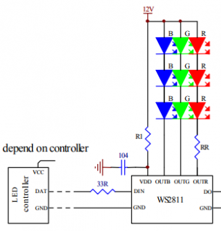
From the WS2811 spec:
Capture2.png

Caution here: VDD is not 24V in your application, it's ~5V due to the appropriate series resistor from the power supply to the VDD pin.

Capture.png

What the appropriate resistor value is for 24V power, I don't know. For 12V power, R1 is 2K7 [although a preliminary WS2811 spec stated 3K8].
There seems to be an internal LDO divider resistor. Perhaps someone else on this forum knows more detail.

Regards,
Paul
 
Hey Paul, thanks for sharing this. Between those two links I was having a hard time following though. I don't have too much experience working with LED strips yet. The strips that I have are very similar to the NeoPixels aside from the 24V rating. So I started with following along the Adafruit guide: https://learn.adafruit.com/adafruit-neopixel-uberguide/powering-neopixels

It was this line at the end of that page that led me to exploring the power questions I've posted above:
The 3.3V signal from the microcontroller may not be “loud” enough to register with the higher-voltage device. The manufacturer recommends a minimum signal voltage of 70% of the NeoPixel voltage.

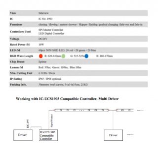
The supplier I got the strips from more often ships them with a DMX controller, but has listed them as working with IC-UCS1903 Compatible Controllers. That had me thinking that the 5V output of the OctoWS2811 would do the job, but wasn't sure if there needed to be anything else added in between.

Any other considerations here would be appreciated or a bit more of an explanation to help me understand what you've detailed above would be great. My main concern at the moment is causing any damage to the strips if I try to power them up using the setup I've noted.

Thanks again,
Jeff
 
One more follow up here. I'm curious about compatibility between the OctoWS2811 and the Teensy 3.6. In reading the OctoWS2811 Adaptor page, it talks about the pins to use to be able to stack the 3.6 with the adaptor board. That led me to figure they were compatible. However, I looked at the page for the Teensy 3.6 again and noticed that the 3.5 is listed as 5V tolerant but the 3.6 is not. Can I provide 5V to the 5V pin on the adaptor board (in my case using a regulator to step down from my 24V power supplies), cut the VIN-VUSB pads and be alright using the 3.6? Or should I use a 3.5 instead?

Thanks!
 
The octows2811 board has a level shifter (a pair of 74AHCT125's if memory serves) that converts the 8 3.3v pins from the Teensy that are sent in parallel to the 5v for the LEDs fast enough for the WS2812B LEDs. Because there no separate clock signal, WS21812B leds use a fixed time for programming each light. WS2812B leds are unidirectional, you never get input from the LEDs.
 
Thanks Michael. What about using the WS2811 led strips I have? They use both the data and clock wires.
 
Thanks Michael. What about using the WS2811 led strips I have? They use both the data and clock wires.

I don't know anything about them, perhaps somebody else does. But having a separate clock wire eliminates a lot of the problems of WS2812B/neopixel strips. Of course, when you get up to 1,800 LEDs you have to be more careful about power distribution, etc.
 
Thanks Michael. What about using the WS2811 led strips I have? They use both the data and clock wires.
If it has data and clock lines, it won't be a ws2811 chip, but perhaps a ws2801 chip (or SPI like chip). ws2811 chips use a strict timing signal on the data line to remove the need for the clock line.
 
Thanks for bringing that up. The specs on the strips I bought clearly indicated them as WS2811 strips. So I guess that could have been incorrect. When I saw that they had four wires, a blue and green, I figured the fourth was a clock one but hadn't realized that could mean they aren't WS2811. Is it possible that fourth one could be a data ground wire?

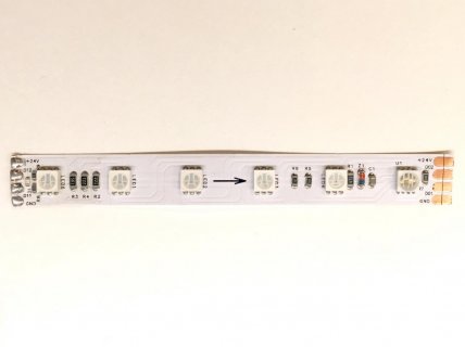
I just cut a section of the strip out of it's weatherproof casing. Was hoping it would be evident what type of strip I'm working with once I had, but looking at it now I'm not sure. Are you able to tell what I'm working with from the pic attached here?

Also attaching another pic of some of the other specs on the strips.
LED-strip-image.jpg
LED-strip-specs.jpg
 
Here's a UCS1903 datasheet that I found:

http://www.bestlightingbuy.com/pdf/UCS1903 datasheet.pdf

According to that, there is an extra pin to select data speed. Connect to VDD for low speed, leave floating for high speed. Are there chips like that on the strip somewhere? I don't see any in the photo, but they say minimum cutting length is six LEDs, so I would think there would be one driver chip per six LED packages.
 
Last edited:
I don't see any chips and have cut out four lengths of six LEDs. Each six LED segment looks the same as the others (what I have pictured above). I've reached out to the supplier asking if they can provide me with further product information.

Presumably, the labels on those pads look like they might be inaccurate. That D11 and D12 should actually have an I not a 1 as the second digit and be referencing Digital Input 1 and 2. With D01 and D02 being the digital outs. I'm not sure what to make of that second set of I/Os.

My next step of troubleshooting (unless the supplier beats me to providing some helpful answers), is to hook up one of those smaller segments and use the FastLED library to try and specify each chipset with the hope one of them provides the anticipated results. Will report back with what I'm able to figure out. Appreciate any other thoughts in the meantime though (as well as the ones already provided).
 
Looking a little closer at the photo, I see the rightmost LED is different. It has 8 pins instead of 6. I'm betting that LED package has the controller built into it. I would try FastLED, set to UCS1903, attached to DI1, leaving DI2 floating. And if that doesn't work, attach DI2, and leave DI1 floating.
 
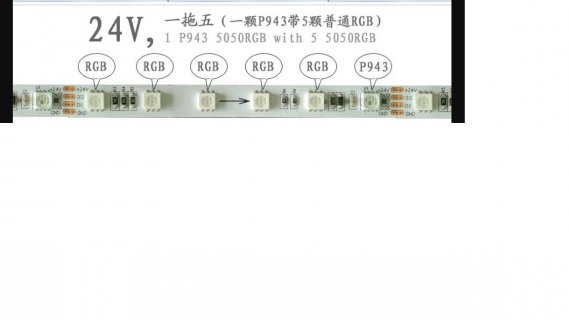
the six led configuration with the last being an 8 pin 5050 rather than 6 pin like the others in the strip looks a lot like the P943 setup, see image below.
led943.jpg
 
Hey again. Good catch on both accounts. It likely is the P943 setup. Your posts have helped me made progress. Here's where I'm at so far...
- Connected an Arduino Uno to a single cut length (6 LEDs).
- Set up a basic circuit with a capacitor (1000µF, 50V) bridging power/ground and a resistor (510ohm) connected to data on the strip (DI1).
- Set the chipset as UCS1903 in the FastLED example Cylon.
- Powered everything on in the sequence: power, ground, data.
- It worked!
- Changed the chipset to WS2811 and powered everything up again.
- It worked!
* Note, for both instances above... connecting power lit all LEDs blue until the data signal was connected and the colors began to cycle.

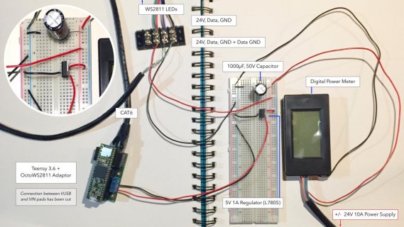
At that point I tried moving everything from the Arduino to the Teensy setup, including the larger LED strip. This is where I've gotten stuck. I've attached a photo of how I wired everything together. One point to note, is I can't tell which cable from the LED strip is connected to DI1 without damaging it's casing. I heard back from the supplier but they won't be getting back to me with additional specs for another day or two. So when I tried connecting this setup I tried connecting data to both the green and blue wires from the LED strip. Here are the other steps I took.
- Connected the wiring as detailed in the attached photo (not shown in the photo, the LED strip with 1788 LEDs).
- Loaded the example code to the Teensy with the only modifications being the NUM_LEDS_PER_STRIP set to 300 and the NUM_STRIPS set to 1.
https://github.com/FastLED/FastLED/blob/master/examples/Multiple/OctoWS2811Demo/OctoWS2811Demo.ino
- Powered everything on together.
- The entire strip (all 1788 LEDs) turned blue for maybe a half second then all turned off.
- Tried changing the data wire coming from the strip and tried again. Same result.

All that said... notice anything in my setup that needs changing? or have any advice on what my next steps should be?
Appreciate the help.
Thanks!
Jeff
24V_OctoWS2811_Wiring.jpg
 
It looks like you might have DI2 attached to the positive side of your 24V power supply? That is probably way too much voltage for that pin. In the UCS1903 datasheet I attached above, it should either be floating or +6V. Not knowing the exact chip, I would suggest keeping it no higher than +5V, but assuming you want high speed, it should be floating. Attaching +24V to a data pin probably fried something.
 
The green wire coming from the LEDs isn't attached to anything. Just looks like it is in the pic. I should have clarified that. Seeing as I don't know which of those two wires is attached to DI1, I tried both, with only one connected at a time and the other floating. So I don't think I've fried anything. Notice anything else?
 
To follow up on where I am with my troubleshooting plans...

I just tried the same setup but swapping out the larger LED strip back to the 6 LED strip I was using before. Same result. Full blue for a moment, then turned off. Reprogramming the Teensy down to 6 LEDs went fine. So I don't think there's anything wrong there.

Going to move on to trying something different with the code and the wiring. On the code side, I'm going to try Paul's OctoWS2811/BasicTest example instead of the OctoWS2811demo example in the FastLED library. Looks like you only need to specify ledsPerStrip and not how many strips or what pin it's connected to. So I'll set that to 6 LEDs while testing on the smaller strip for now and if I am getting the data pin on the strip correct and have the other wire shown above floating, then it should be configured for 800kHz. I used the green wire out of the CAT6 cable, which looks to be what I should use if only using a single strip.

On setting up the wiring, I'm going to try connecting the supply and capacitor straight to the terminal block and split off the power to the regulator/Teensy from there.

Any suggested changes to those plans or confirmation I'm on the right track would be appreciated! Thanks

* Also to note. I'm running the latest versions of Arduino, Teensyduino and the OctoWS2811 library.
 
UCS1903 seems to have slightly different timing from WS2811. I wonder if that could be causing problems for longer strips?
 
I'm up and running with the OctoWS2811 Basic Test example! Seems like it was wiring issues I was experiencing. Connecting the power supply and capacitor straight to the terminal block seemed to do the trick. Although, I did have troubles with the FastLED OctoWS2811 example. I've posted in that forum for help. Would rather use that as there isn't much documentation for Paul's example. I'll start a new thread for help working with that. Thanks again!
 
Status
Not open for further replies.
Back
Top