You are using an out of date browser. It may not display this or other websites correctly.
You should upgrade or use an alternative browser.
You should upgrade or use an alternative browser.
PCB-production
- Thread starter Frank B
- Start date
- Status
- Not open for further replies.
I got the new boards yesterday (again perfect quality from OSH-Park); they are working now.
Great. I soldered 5 x 23LC1024.
A little thing that I underestimated is that the buffer ( SN74HC367D ) prevents higher speeds . The maximum speed is only 6MHz(? without buffer and with 2 x 23LC1024 it was 20MHz) . Perhaps the layout plays a role too.
But I'm happy with it, it's good enough for my project.
(But let me ask, are there better tri-state buffers ? Ideally with inverted "enable" ?)
@Paul: I placed an order with delivery to you: OSH-Park #1PpzvYXZ
(Easier & faster than walking to the post-office
https://github.com/FrankBoesing/memoryboard
Last edited:
PaulStoffregen
Well-known member
Does it work at 24 MHz if you just replace the buffer with wires?
Try 74LCX126.
It has about 10X less propagation delay than 74HC367, and the tri-state control is active high, so you can avoid that extra inverter chip.
Likewise, you can get the 3:8 decoder as 74LCX138, for much less propagation delay.
are there better tri-state buffers ? Ideally with inverted "enable" ?
Try 74LCX126.
It has about 10X less propagation delay than 74HC367, and the tri-state control is active high, so you can avoid that extra inverter chip.
Likewise, you can get the 3:8 decoder as 74LCX138, for much less propagation delay.
PaulStoffregen
Well-known member
If you make another board rev, please also consider adding pull-down resistors on Teensy pins 8, 16 and 17. Until you initialize those pins, they are high impedance. Resistors will keep those pins low, to prevent the decoder from accidentally asserting chip select to any of the memories.
It's also common practice to place a 0.1 uF (or even 10 nF) capacitor between 3.3V to GND near each chip. The length of the wires and especially the loop area between the wires and the capacitor and the chip matters much more than the actual value of the capacitor. One capacitor shared between 2 chips is usually fine, if the wires are short and run directly without a large loop.
It's also common practice to place a 0.1 uF (or even 10 nF) capacitor between 3.3V to GND near each chip. The length of the wires and especially the loop area between the wires and the capacitor and the chip matters much more than the actual value of the capacitor. One capacitor shared between 2 chips is usually fine, if the wires are short and run directly without a large loop.
If you make another board rev, please also consider adding pull-down resistors on Teensy pins 8, 16 and 17. Until you initialize those pins, they are high impedance. Resistors will keep those pins low, to prevent the decoder from accidentally asserting chip select to any of the memories.
It's also common practice to place a 0.1 uF (or even 10 nF) capacitor between 3.3V to GND near each chip. The length of the wires and especially the loop area between the wires and the capacitor and the chip matters much more than the actual value of the capacitor. One capacitor shared between 2 chips is usually fine, if the wires are short and run directly without a large loop.
Thank you!
I had tried to keep the component count low - my SMD soldering skills are not good (my eyes..).
I make a new rev. I'll swap top&bottom too, because I realized that it is not possible to add more memory later if the board is soldered under the teensy.
my SMD soldering skills are not good (my eyes).
You'll look like a nerd but it'll be worth it ;-)
http://www.doneganoptical.com/products/optivisor
Constantin
Well-known member
You'll look like a nerd but it'll be worth it ;-)
http://www.doneganoptical.com/products/optivisor
Sir, are you calling me a nerd? I wear my optivisor with pride.
Now where is that white gauntlet so I can challenge you to a duel?
But seriously, the optivisor really helps with inspecting solder joints and/or dealing with components that have very faint laser markings instead of painted ends (for example, PMEG3020 diodes in a cut tape array). Even then, I have to use a flashlight held at an angle to ensure I got the markings right.
epicycloid
Well-known member
You'll look like a nerd but it'll be worth it ;-)
http://www.doneganoptical.com/products/optivisor
Another alternative to the OptiVisor, if you haven't seen them, are MagEyes. Multiple models, including an ESD version if you need it. Most are just a featherweight open-back clip-on-your-head-style, but they also offer a full-headband style too.
I like them a lot better than the OptiVisor because they are wide open (as in less claustrophobic, better peripheral vision), and weigh nothing.
That said, their website can be confusing, "Double Hi" and "Double Lo" refer to the fact that most models come with two lenses included (another reason I like them over the OptiVisor), and the pair is either the low power pair, or the high power pair...
Lens #2 = 1.6x working distance approximately 12"-14"
Lens #4 = 2.0x working distance approximately 10"-12"
Lens #5 = 2.25x working distance approximately 7"-10"
Lens #7 = 2.75x working distance approximately 4"-7"
epicycloid
Well-known member
My workplace is (nearly) littered with those optivisor things but mageyes look like they much less make you look through a fairly restricted window - might have get a pair in here and see if anybody else here likes them.
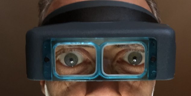
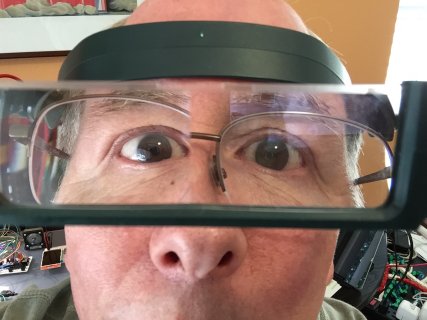
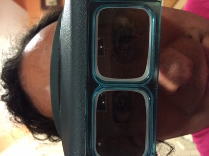
Nice hijack fellas, coulda used more photogenic models tho
Nice hijack fellas, coulda used more photogenic models tho
epicycloid
Well-known member
I've used both, and I do have to say that once I discovered the MagEyes, I've never used the OptiVisor's since.
It was a "staring contest" not a beauty contest. Hmm... I wonder what the average age of Teensy users/buyers is? Pretty sure the demographic is kinda skewed. Just a hunch.
It was a "staring contest" not a beauty contest. Hmm... I wonder what the average age of Teensy users/buyers is? Pretty sure the demographic is kinda skewed. Just a hunch.
OMG!!! Great photos. I suspect that I look better with such a thing  I buy one.
A Question, there is not much room for three additional resistors and a couple of capacitors.
I think it would be possible with 0603. I'm a bit nervous.. is 0603 manageable for SMD beginners like me?
It looks like mouse droppings .. no..much smaller..
A Question, there is not much room for three additional resistors and a couple of capacitors.
I think it would be possible with 0603. I'm a bit nervous.. is 0603 manageable for SMD beginners like me?
It looks like mouse droppings .. no..much smaller..
Last edited:
I suspect that I look better with such a thing
QUOTE]
I am not going to comment on that ;-)
Yes, 0603 can be managed fine. Just make sure you have a good flux pen when soldering these by hand. The flux pen is quite the key to success when manually soldering small and fine pich components.
Yes, but buy solder paste. Put two blobs of it on the pads, place 0603 and hit with a sharp solder tip.
Better yet, buy paste and a hot air soldering pistol
http://youtu.be/vva2t21sOAs
I bought one (same as Dave in the video, but different company) and I love it! Only like 50 bucks.
I've done 0402 with relative ease. Grain of pepper size
Better yet, buy paste and a hot air soldering pistol
http://youtu.be/vva2t21sOAs
I bought one (same as Dave in the video, but different company) and I love it! Only like 50 bucks.
I've done 0402 with relative ease. Grain of pepper size
Last edited:
Ok.. i try it.
Schematic:
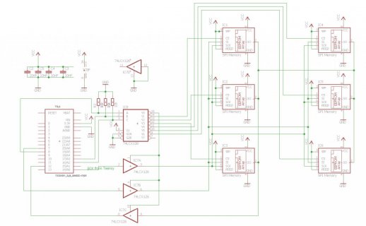
Eagle-Files:
https://github.com/FrankBoesing/memoryboard
What do you think ? Is this better ?
I tried to maker shorter connections to the caps, but no chance... it has 4 of them (which value ? 10nF or 100nF ? or 47?)
Maybe it's possible with 4 layers.
Edit:
Link to shared project @ OSH-Park (but i have not ordered yet) :
https://oshpark.com/shared_projects/61B9Gq8f
Schematic:

Eagle-Files:
https://github.com/FrankBoesing/memoryboard
What do you think ? Is this better ?
I tried to maker shorter connections to the caps, but no chance... it has 4 of them (which value ? 10nF or 100nF ? or 47?)
Maybe it's possible with 4 layers.
Edit:
Link to shared project @ OSH-Park (but i have not ordered yet) :
https://oshpark.com/shared_projects/61B9Gq8f
Last edited:
PaulStoffregen
Well-known member
The schematic looks good.
Yeah, 2 layers with parts on both sides creates a lot of challenges for routing the traces! But the electrons do not know or care about the difficulty in PCB routing! Still, having those capacitors close, even if the traces aren't ideal, is a lot better than no decoupling caps at all.
If you're planning on publishing these files for other people to build, I would recommend adding pin 1 marks in the silkscreen for all the chips. Without them, it's very easy to place a chip backwards! Rectangles around the resistors and capacitors are also helpful, to avoid a common mistake where 4 close pads (like R1 and R3) can be mistakenly placed with the parts on the wrong pairs.
The schematic looks good.
Yeah, 2 layers with parts on both sides creates a lot of challenges for routing the traces! But the electrons do not know or care about the difficulty in PCB routing! Still, having those capacitors close, even if the traces aren't ideal, is a lot better than no decoupling caps at all.
If you're planning on publishing these files for other people to build, I would recommend adding pin 1 marks in the silkscreen for all the chips. Without them, it's very easy to place a chip backwards! Rectangles around the resistors and capacitors are also helpful, to avoid a common mistake where 4 close pads (like R1 and R3) can be mistakenly placed with the parts on the wrong pairs.
I updated a few things including the slikscreen, and the vias are covered now.
Thank you!
C5 is unfortunately very close to the pins , but I can not do better.
I am very curious about whether this new rev is better and if it works "full speed" for the faster flash too.
https://oshpark.com/shared_projects/DHfqAywO
Edit: Updated Github
Edit: Ordered... waiting another 3-4 weeks..
Last edited:
Constantin
Well-known member
defragster
Senior Member+
... I wonder what the average age of Teensy users/buyers is? Pretty sure the demographic is kinda skewed
I doubt I skew the demo down . . . my wife bought me a pair of the mageyes (some years back).
Constantin - I found your eyes - you look nothing like your avatar . . . at least I have white top like mine - so far.
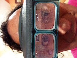
I've been buying photoshop for years - finally something I couldn't do with MSpaint - though it did make my avatar's feet pop out too.
Speaking of Eagle ... and the thread context . . . I need to get back to learning that soon.
Last edited:
Constantin
Well-known member
Well done! I can see the light! Or something like that. Now how about finding my brain...
Anyhow, eagle is fun. Something new to learn every day. Though I have stopped for now at 6.4 on account of the changes in 6.5 and up that made all sorts of parts in the library that are known good to become non-compliant and unhappy.
Anyhow, eagle is fun. Something new to learn every day. Though I have stopped for now at 6.4 on account of the changes in 6.5 and up that made all sorts of parts in the library that are known good to become non-compliant and unhappy.
It bothered me ...
I continued trying and finally I managed to accommodate the missing capacitors.
There was even room for an LED that is connected to the previously unused CS7 . Maybe it's quite handy . It is optional.
Paul, how much MCD has the teensy LED ?
So , now that was certainly the last version - For I have no desire to tinker it.
https://github.com/FrankBoesing/memoryboard
https://oshpark.com/shared_projects/A1AbiQiu
Last edited:
Constantin
Well-known member
Minor comment - try running power lines such that they run through the positive end of the decoupling capacitor before they hit the local device that the capacitor is for. That allegedly helps keep the noise inside the device.
- Status
- Not open for further replies.


