Pins 24 to 33 and others

Status
Not open for further replies.

fedekrum

Member
Sorry if this is a more than basic and repeated question, but I cant find the answer in the forums (or may be there are some english words missing in my vocabulary :) to search for )

I was abel to weld pins to the borders of my teensy 3 but...

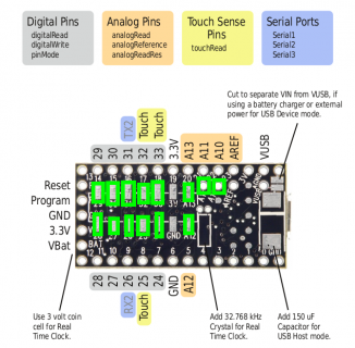
What is exactly the thing I have to weld to connectors 24 through 33 to have pins there ? (a picture of it, even a link to someone selling it at ebay will be appreciated.
 
pinout5b.png

http://www.pjrc.com/teensy/pinout5b.png

Wires or get a breakout board.
 
Last edited:
Wires or get a breakout board.

While you can do wires, my preferred solution is a 2x7 unshrouded pin header instead. See this link to Digikey for a selection.

If you prefer other vendors or live outside the US, look for a unshrouded pin header with 2 rows of 7 pins each with 0.1" spacing between pins (i.e. 2.54mm). The only other detail is the length of the pin relative to the board, i.e. making sure that the other, straight pins you want to solder on have about the same length as the SMD-mounted pins on the 2x7 header. One option is to look up manufacturer part numbers on digikey and then use them in the search engine of your favorite vendor.
 
Ummm. I'm a bit confused by your response. Is this a auto-correct failure? You do know the meaning of rape, no?
 
"the easy cheap solution"
Buy a larger set of headers and run copper soldered wires to e'm.
 
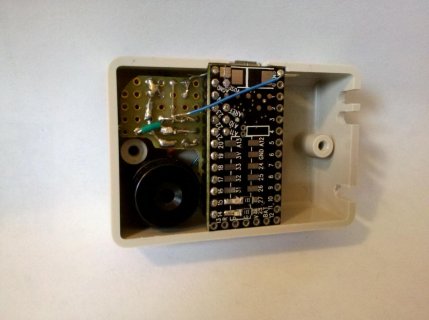
One of my T3s is mounted flush behind the front panel of the project box. I've soldered a surface mount LED and a surface mount resistor in series between each of two pairs of pads. Obviously, this is not a general solution, but mounting the Teensy against the front panel is an approach I'd use again.

The picture may be a little hard to see. The resistors are labeled 331. The light colored blobs next to them are LEDs. One LED/resistor pair connects pin 27 to pin 15. The other pair connects pin 28 to pin 14. I figured out which pin needed to be high and which pin needed to be low by trial and error, though there is actually a tiny mark on the LEDs.

t3_smt_leds.jpg
 
How do the Breakout bords contact these inside connectors? because all I have seen, need something solded on them. Am I missing something?
 
When designing a breakout board, it's a good idea to oversize the 14 holes for the interior connections. On one I made for testing, I made the 28 outside holes 0.038 inch, which is just barely large enough for a normal header pin. On the interior holes, I made them 0.050 diameter.

When you assemble the thing, you first need to solder a 14 pin J-lead header to the Teensy3. It will not align perfectly. The larger holes allow for a small misalignment.

To complete the assembly, the easiest way involves putting the two header strips into the 0.038 holes with the short side facing up. Then place the Teensy3 onto the board. The 7x2 header that's already soldered to the Teensy3 will mate with the 0.050 holes first. Then because the two header strips on the outside are not soldered, you can wiggle the Teensy3 into position onto the 2 loose header strips. If your placement of the 7x2 header was highly accurate, everything will be a loose fit. If it's off a little, hopefully this way gives you the best chance get things lined up and press the Teensy3 into position with all 28 other pins.

Also, you might consider whether you really truly need any of those bottom-side signals. Some projects really do need a lot of I/O. I know it's really painful to have a chip with so much I/O but no way to access those other pins (eg, Arduino's larger Mega & Due have much inaccessible pins). But for most projects, the main pins on the top side are plenty, and they're much easier to access.
 
How do the Breakout bords contact these inside connectors? because all I have seen, need something solded on them. Am I missing something?

No you are not missing something. You need to solder header pins to connect to the pads. The link I provided, includes the header pins.
 
Status
Not open for further replies.
Back
Top