
Hello everyone,
Summary
I am trying to use a Teensy 4.1 to talk over SPI to an AD7147 (a capacitive-to-digital converter (CDC)). However, the connection is inconsistent: the system will fluctuate between receiving the expected data and receiving 0s.
Setup
Minimal example and behavior
I am using a short test script (shown below) that simply tries to read the device address from the AD7147. The expected behavior is the AD7147 will return its device address and this will be printed on the Serial monitor.
The behavior I see is that sometimes the correct device address is printed and sometimes 0 is printed. Pushing the ground wire around will sometimes (not always) change whether it’s working or not working. There are a few things that I’ve found cause the device address to be returned consistently:
Here are a few other notes:
Based on this behavior, my suspicion is that my chip_select sometimes does not get pulled LOW, perhaps due to some problem with my grounds? Does anyone have thoughts on what may be going on or suggestions for how to debug further?
Thank you so much!
Here is my setup and test script:


Summary
I am trying to use a Teensy 4.1 to talk over SPI to an AD7147 (a capacitive-to-digital converter (CDC)). However, the connection is inconsistent: the system will fluctuate between receiving the expected data and receiving 0s.
Setup
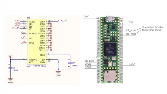
- My setup is a Teensy 4.1 on a breadboard, with the AD7147 sitting on a separate test PCB that I made. The separate test PCB also has 2 other devices on the same SPI bus and communication with these devices is working.
- The breadboard and test PCB are connected with jumper wires. The wires are no more than ~6 inches long.
- I'm using Teensyduino 1.59.0, Arduino IDE version 2.3.2, Ubuntu 22.04
- A picture of my setup is shown below
Minimal example and behavior
I am using a short test script (shown below) that simply tries to read the device address from the AD7147. The expected behavior is the AD7147 will return its device address and this will be printed on the Serial monitor.
The behavior I see is that sometimes the correct device address is printed and sometimes 0 is printed. Pushing the ground wire around will sometimes (not always) change whether it’s working or not working. There are a few things that I’ve found cause the device address to be returned consistently:
- If I disconnect the Teensy ground from the test board ground (i.e. the AD7147 is no longer grounded), the correct device address is returned continuously
- If I probe the chip_select line with the oscilloscope probe, the correct device address is returned continuously
- When I unplug the chip_select line, the correct device address is consistently returned a single time
Here are a few other notes:
- Using certain digital pins on the Teensy for the chip_select seem to affect the behavior. For example, I’ve found that using pin 25 does not work most of the time, whereas using pins 7 and 8 work most of the time.
- I am using 10k pullup resistors on all chip selects
- I have confirmed that all of my devices have correct tri-state behavior on MISO (https://www.pjrc.com/better-spi-bus-design-in-3-steps/)
- I’ve looked at all the signals on an oscilloscope. Everything looks correct, but it is difficult to look at the signals when the system is NOT working because as I said above, probing the chip_select seems to make things work.
Based on this behavior, my suspicion is that my chip_select sometimes does not get pulled LOW, perhaps due to some problem with my grounds? Does anyone have thoughts on what may be going on or suggestions for how to debug further?
Thank you so much!
Here is my setup and test script:
C++:
#include <stdio.h>
#include <SPI.h>

#define MOSI1 26
#define MISO1 39
#define SCLK1 27
#define CS_ACCEL0 21
#define CS_ADC0 20
#define CS_CDC0 25

#define DEVID 0x17

int chip_select = CS_CDC0;
int all_chip_selects[3] = {CS_ACCEL0, CS_CDC0, CS_ADC0};

uint16_t received_id = 0x00;

void setup()
{
  Serial.begin(57600);
  while (!Serial);

  for (int cs : all_chip_selects) {
    pinMode(cs, OUTPUT);
    digitalWrite(cs, HIGH);
  }

  SPI1.setMISO(MISO1);
  SPI1.setMOSI(MOSI1);
  SPI1.setSCK(SCLK1);
  SPI1.begin();  //Start SPI1 communication

  delay(1000);
}


void loop()
{
  Serial.println("-------");

  uint16_t ControlValue;  // i.e. command word, see datasheet p. 34

  // DEVID & 0x03FF puts DEVID into the last 10 bits of the 16 bit control value
  Serial.println(DEVID & 0x03FF, HEX);
  ControlValue = 0xE400 | (DEVID & 0x03FF);

  SPI1.beginTransaction(SPISettings(5000000, MSBFIRST, SPI_MODE0));
  digitalWrite(chip_select, LOW);

  delayNanoseconds(5);  // following CS falling edge to first SCLK falling edge in datasheet p. 6

  SPI1.transfer16(ControlValue);
  received_id = SPI1.transfer16(0x0000);

  delayNanoseconds(15);  // following SCLK rising edge to CS high timing in datasheet p. 6

  digitalWrite(chip_select, HIGH);
  SPI1.endTransaction();

  Serial.print("Sent: "); Serial.println(ControlValue, HEX);
  Serial.print("Received: "); Serial.println(received_id, HEX);

  Serial.print("Received ID: ");
  Serial.println(received_id);

  delay(100);
}
Attachments
Last edited: