Teensy 3.0 - driving an SSD1289 with utft

Status
Not open for further replies.
I have mine connected to the 3.3V pin on the Teensy 3.0 (Between AGND and pin 23) using a 4.7K pull up resistor for safety, not sure if it needs it :)
 
Last edited:
First, while pin 13 does have the LED on it, there's no reason to skip it. it doesn't interfere with normal pin usage. I'd advise sticking to 0-15 just for simplicity sake to get the display working initially. After you get it working once, and know the hardware itself is functioning, you can start moving pins to free up possibly needed ports on the teensy 3 that might be needed for other things you'd like to add to your project.

Second, RD, at least on my display, doesn't need a pull up resistor. I just have it connected to 3.3v and it works fine.

Also, if I may ask, which utft library did you download? The one I posted, the one dawnmist posted, or the one on the utft site? I'd really need to know exactly which one you're using, to give you pointers on what to try when it doesn't work.
 
Last edited:
Thanks, Ex! I tried hooking Rd to 3.3V with a 2.2k resistor but all it does is flash completely black a couple times and go back to just being backlit.

Q, the library I'm using is the zip file Dawne posted here: http://forum.pjrc.com/threads/18002...SD1289-with-utft?p=23036&viewfull=1#post23036

The only code I've changed so far is the pins in HW_Teensy3.h and the initialization code at the top of the sketch (I'm trying the UTFT_ViewFont one) but I'm going to try starting fresh with that lib and not skipping 13 and seeing what happens.
 
In my testing, I was using the demo example sketch included in utft/arm for 320x240.

I haven't personally used dawnmist's library, just the one I modified, but from looking at it, changing the 'if 0' to 'if 1' in hw_teensy3.h should be all you have to do. You want to make sure when you compile, it says 'using pins 0-15'.

The rest of the library usage is the same as with any other display with utft.


I will note that the display must be powered on, and wired, when the teensy reboots and starts running code, for it to initialise. Otherwise you just get the backlight. If you disconnect the display or lose power to it, you'll have to reboot/power cycle the teensy to get it working again.
 
I used the UTFT/ARM 320x240 demo, and only changed the myGLCD part of the sketch because when I compile, it already says "using pins 0-15". Power is constantly on through the USB cable. Still just backlight with unlit flashes at times. Does that mean it's probably not an SSD1289?
 
Where did you get it, can you send a link? Can you post a picture, front and back? Does the PCB silk screen have a pin out on it?

We will get you there, I know how frustrating it is to have a new toy and not be able to get it working! :0)
 
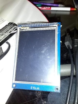
Front:
front.jpg

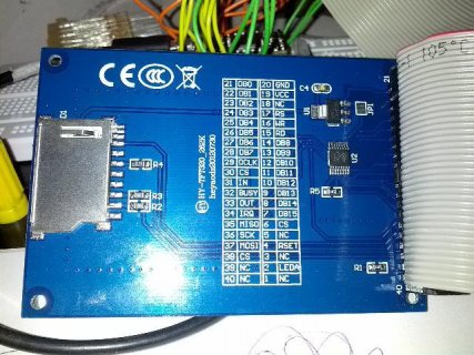
Back:
back.jpg

And here's the link to the ebay listing:
http://www.ebay.com/itm/281008929016

The pin configuration in the ebay ad confused me for a second, but the columns are just switched because it's looking at the board from the screen side. The numbers are all different, but the pin labeled LEDA is lighting up the backlight so the board's listing should be right.

Thank you so much for your help!
 
i'm honestly at a loss as to what to suggest. About the only things that come to mine is to try the library I posted earlier in the thread.. It SHOULD be the same as the one dawnmist posted, except that its just hard coded for pins 0-15 without using defines. And also, to double or triple check your wiring, especially the ones defined in library init in the sketch, and make sure RD is attached to 3.3v

Actually one thing that does jump out at me is make sure you're using the right CS pin. There are 3 listed in the pinout on your LCD.. one is for the touch screen, one is for the SD card reader, one is for the LCD.. going back to your ebay listing you linked in the pipgirl thread, the pin 6 one seems to be the one that goes to the LCD. Though the numbers are reversed from those listed on your ebay auction.

I'm betting this is just a wiring problem now actually.
 
Last edited:
Hrm. I did plug in that right CS pin, and RD is connected straight to 3.3V and still nothing. I've checked and rechecked the init pins and data connections (though would switched data lines keep any image from showing up or just scramble the image?).

I feel like it's either something stupid, or the lcd board is fried. The LED on the teensy lights up like pin 13 is receiving a signal, but nothing ever shows up on the lcd. It doesn't even flicker anymore. I guess if all else fails, I can use the lcd as a backlight for my project.

The only other thing I can think of is that the IDE cable that I'm using to bring all 20 pins out so I can use jumper wires is messed up.
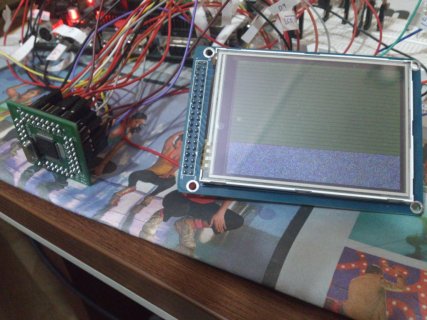
Thank you again for your help.
 
I have the same breakout but it has a different screen attached. I have checked my connections and they are as follows for the TFT (going by the silk screen):

RS - Pin 17
WR - Pin 16
CS - Pin 6
RST - Pin 4

These numbers as per silk screen on the PCB. FYI I have another PCB with exactly the same pin out but the pin numbering for pins 1-20 are reversed, the same as that shown in the ebay details, 21-40 are identical. Both my screens connect to the rig shown in the pictures and work.

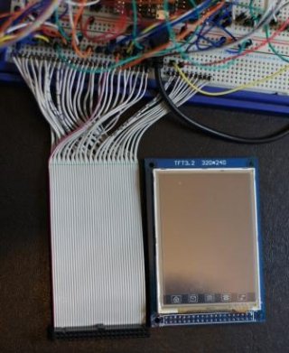
To clarify here are some pictures:

IDC & Pins.jpgOverview.JPG

When the screen is plugged in it covers the ribbon. The left most core of the ribbon is pin 21 which is the red core. If you go by the info on ebay the next core is pin 1; if you go by the silk screen on the PCB it is pin 20.

Following the ebay numbering then my connections to the bread board are from left to right 1-40, going by the silk screen they are 20-1 then 21-40.

If you use the ebay numbering to make things easy, pins 1-40 left to right in the picture above on the right, the connections would be:

RS - Pin 4
WR - Pin 5
CS - Pin 15
RST - Pin 17

ie Pin 20 on the silk screen is shown as pin 1 on ebay, and so on:

Silk Ebay
20 1
19 2
...
2 19
1 20

Pins 21-40 are the same on both the silk screen and ebay making the ebay details easier to follow when you get to playing with the touch.

An extract from my sketch:

// UTFT Parameters:
// Model
int tftRS = 20; // Register Select
int tftWR = 21; // Write
int tftCS = 22; // Chip Select
int tftRST = 23; // Reset
UTFT myGLCD(SSD1289, tftRS, tftWR, tftCS, tftRST);

// Touch Screen
int tchClk = 28;
int tchCS = 27;
int tchDIn = 26;
int tchIRQ = 25;
int tchDout = 24;
UTouch myTouch(tchClk, tchCS, tchDIn, tchDout, tchIRQ);

If I have not fried your brain I hope this helps you to get it going :0)
 
Last edited:
Thanks, Ex! I went back and looked at the pins but it was hooked up just like you described. So I checked the IDE cable with an LED, to make sure the connections were solid. Turned out that the middle IDE connector (which I had it plugged into) had 2 bad connections just on one side. One was completely out and one would flicker. Checked the end one, and it was fine. Plugged it all in, uploaded the sketch, and still nothing. I have checked and rechecked the pins several times and am ready to throw this thing. Could the shoddy connection have messed something up in the LCD?
 
At this point in time IMHO it's either a bad display, or wiring issues, possibly caused due to incorrect pinouts listed.

If it was me, the next step would be to separate the LCD from the adapter board where you can get to the 37 pin ribbon cable coming out of the LCD, then get an ohm meter and match the pins on it to the pins on the adapter board. I can post the pinout/datasheet for the LCD itself when I get home if you don't already have it.
 
Just wanted to contribute my 2 cents.
I too was having the same problem that Qumefox had when he first posted
DSC_0314.jpg

I've interfaced this LCD to an LPC2148.

Managed to find out the problem. At first, I thought 2 jumpers were shorting, or that I had mistakenly swapped data lines. These are of course the first things you should check, and that is what i did, still no go.

I used a USB-based digital scope to check EACH and every line ONE at a time, turns out that one of the data lines wasn't pulsing from peak to peak since there was a capacitor across it !! A saw-wave was being output at this data line.

My advice:
1) Connect all lines to your micro-controller. RD may be pulled up to Vcc via a 330ohm resistor, if no read is required in your application.
2) Keep CS high at all times. This is just a precaution.
3) Pulse each and every line individually, at a minimum of 10kHz, and check on a scope
4) I don't really agree, but keep all jumpers, wires short in length
5) Make sure your CS line pulses too !!

DSC_0321.jpg
 
Hi everyone,

I finally got around to trying to optimize the writes on the data bus, and working out how to write to non-consecutive pins on a port without altering other pins on that port. Be aware that there is a licence change in later versions of the UTFT library from LGPL to CC BY-NC-SA 3.0, which makes the newer versions of the UTFT library unusable for commercial applications (new license's summary here: http://www.henningkarlsen.com/electronics/resource/licenses/CC_BY-NC-SA-3.0-Summary.pdf). That's not going to affect me, but I figured I'd make sure people knew and apply the changes to both versions :). The header file can be used in both the old LGPL 2.01 version and the newer 2.51 library version.

Individual file
I've uploaded a modified HW_Teensy3.h header file here that you should be able to just paste into your existing UTFT lib modifications:
http://www.dawnmist.net/teensy/HW_Teensy3.h

Full updated library
LGPL version: UTFT 2.01 with teensy 3 adjustments applied: http://www.dawnmist.net/teensy/UTFTv2.01_Teensy3.zip
CC BY-NC-SA-3.0 version: UTFT 2.51 with teensy 3 adjustments applied: http://www.dawnmist.net/teensy/UTFTv2.51_Teensy3.zip

Edit: you'll need to check the memorysaver.h file and comment/uncomment the screen controller that matches what you're using - the uploaded versions were both set to SSD1289 because that's what I was using.

For both formats
The header file change provides options for connecting the data lines to:
  • Ports C(0-7) & D(0-7) - 2 write cycles, but conflicts with SPI - only use if you're not needing the SPI ports (e.g. if you don't need an SD Card)
  • Ports B(0-3,16-19) & D(0-7) - 3 write cycles, can be used with SPI (it's what I'm now using, and leaves the SPI port available for use with SDFat)
  • User defined pins - this is the old method. It uses 16 write cycles (one per pin), but lets you set the pins to wherever you want them.
When you use it, you'll need to set the PORTS define in the HW_Teensy3.h header file (and if using the USE_USER_PORTS setting, the DB_0 - DB_15 pin numbers as well if you don't want them on pins 0-15). In the 2.51 version, the header file is in the subdirectory "hardware/teensy3". The instructions are all at the top of the header file - let me know if you have any issues or if they're unclear :).
 
Last edited:
I'm sorry I've neglected the UTFT library so long. I've got a 16 bit TFT display and I'm looking at this now.... finally.

Of these 3 schemes, the Ports B(0-3,16-19) & D(0-7) seems the best, since most people will want to access a SD card for graphics. But wouldn't it make more sense to assign D8-15 on the LCD to the D(0-7) pins on Teensy3, so 8 bit mode will get a single optimized port? Or did I miss something on how this works?

For 8-bit, it's set to use the D port pins for both B&D and C&D modes (effectively it uses DB8-15 for the connection, and ignores DB0-7 when in 8-bit mode). This was based on the original arduino instructions for UTFT which said to use the connections for DB8-DB15 (leaving DB0-7 unconnected or simply connected to gnd) if connecting an 8-bit display.
 
Last edited:
Just a final update on this for anyone else that goes through the thread:
  • As of Teensyduino 1.18 (or maybe 1.17 - I skipped that version), the modified UTFT library is now in the list of libraries that Teensyduino can install, using the port B&D pin mappings for 16 bit, and the port D mapping for 8 bit communication.
  • As of UTFT 2.73, the Teensy 3.0/3.1 is now officially supported by Henning Karlsen by default.
This means you no longer need to patch the library to make it work anymore - the patches are all applied for you by default :).

Just make sure you only have one copy of the library - either the one installed by Teensyduino OR one you've put in your Arduino/libraries folder. If you accidentally have both (as can happen if you were already using UTFT and then upgraded to teensyduino 1.18 without checking the list of teensyduino libraries), you'll get a series of compilation errors "multiple definition of..." <some UTFT function> "first defined here" for every UTFT function, because the arduino editor finds both your user UTFT library and the installed teensyduino UTFT library and includes it twice. It took me a little while last night to work out what I was doing wrong. ;).
 
Last edited:
I just spent about two hours figuring out how to get one of these to work and had success.
Tomorrow I'll try the touch part and then post my code for anyone new to this like me.

Btw: anyone have any ideas how to make some room for other devices? When all is said and done (and plugged in) I think I'll be missing about 6-8 pins to complete my project.
I think I may even need to get the SD card running if I want some graphics showing up.
Anyone had success running the TFT, touch, SD all on one Teensy?

Edit: If I run out of pins, would a be a dumb idea to use an Arduino Pro Mini 5v/16mhz to run par of the project and cooperate with the Teensy? Mainly so I can run the TFT as fast as possible. I've never done anything similar to connecting two boards.
 
Last edited:
So I got UTouch running fine. Now going to add SD card.
After that I'll be left with about two or three free pins, but I need atleast an SPI wifi module.
What has to be done to run this display in 8bit? I see in the files that there are 8/16bit pinouts, but I don't know if I have to do anything else.
 
Searching around it seems that it can't be run in 8bit.
I tried disconnecting DB0-7 and using

UTFT myGLCD(SSD1289_8,23,22,3,4);
and
UTFT myGLCD(ELEE32_REVB,23,22,3,4);
 
My understanding - which could easily be wrong - is that while the control chip itself is capable of 8 bit, the people that make up the boards with the chip/screen/sd/touch and sell them cheap on ebay usually wire them up in the 16-bit configuration, so they're physically set by wiring/tracks on the board to 16 bit only. If my understanding is correct, you'd need to get a board set up for the 8 bit data bus if you wanted to use that instead.

And yes, I've got a 16-bit TFT/UTouch/SDFat running together on a single teensy - the sd is on the spi pins, and the touch interface is NOT using the spi pins (so no pins are shared between sd/touch), and I had 4 digital pins left for other use (which was *just* enough for what I needed - they interface to a series of shift registers and a latch reset line for external input).
 
Last edited:
That's pretty much what I thought. But I did read somewhere that it could be a matter of swapping a resistor on the board, so I may look into that.
Thanks for your help!
 
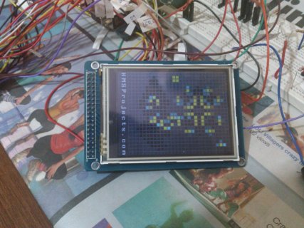
I tested teensy 3.1 withe a 16 bit 3.2 " TFT with Touch (Controller SSD1289). At first i had problems with the display, I took a parallel cable with connector from a old Disk, but I think it was to long or the wires are to near together. Therefore I made a new layout and the display was ok.
I build a two channel osci, I need for one Sample/10 bit 0,25 µs . I can use the Osci in single channel mode to maximal about 30kHz.
I tested the ADC-lib and store the parameters in EEPROM

https://www.youtube.com/watch?v=581HnbvP6PU&feature=youtu.be
 
Status
Not open for further replies.
Back
Top