Teensy 3.0 -> Small-Scale Production

Status
Not open for further replies.

LANman247

Member
I've recently migrated to the Arduino world from programming in C on Atmel micros. I bought the Teensy 3.0 because of its low cost and rapid prototyping abilities, for which it has been wonderful (well done, Paul!). However, I would like to take the project that I have made on it into small scale production - small enough where I wouldn't be pumping out hundreds per week or month, but large enough where fabricating my own PCB would be more economical than batch ordering Teensy's. Essentially I want to take the code that I wrote for the Teensy 3.0 and put it into my own production board, sans the special bootloader and ability for the user to reprogram it, etc.

Here are my questions:
- If I fabricated my own boards with the same chip used on the Teensy 3.0, would I be able to write the hex file I created for my Teensy to the fresh chip via an ISP?
- Is the bootloader on the Teensy 3.0 required for using the hex file generated in the Arduino/Teensyduino environment? (not really familiar with bootloaders)
- Is there a low-cost ISP that I could use to write to the MK20DX128 chip? Would the KwikStik K-40 work?
- Are there any other things that need to be configured on the MK20DX128 to be used with the hex file generated in the Arduino/Teensyduino environment (bits to configure on the chip)?
- Is there anything that I would need to change in the Teensyduino library to achieve this?

Thanks a lot for the help, and thanks a lot, Paul, for your work on the Teensy 3.0!
 
You have a few options....

For very low volume production or initial demo units, sometimes the most sensible solution is simply embedding the $19 board inside your product. Obviously you're not going to do that at substantial production volume. But I always mention this first, because I've seen many idea -> prototype -> production efforts fail because they put all their time and money into the technical aspects, rather than focusing on common sense business.

Every product is different, but usually high volume sales don't happen overnight. Often the best strategy is to simply get products into the customer's hands. Typically sales start slow and grow. Typically you also learn along the way and revise the product based on customer feedback (or new opportunities you discover), so merely getting some initial sales at low volume is often the best approach (unless of course you have some special situation like a large contract to deliver lots of units). Later when you reduce costs, you'll have established sales trends so you'll know it saves money. You'll know *exactly* how much money a cost reduction will save, in fact, because you'll know how many you're currently selling. When you have no sales, cost reductions save absolutely nothing and can cost a tremendous amount if you pursue them at the expense of sales and marketing efforts. This may sound overly obvious, but LOTS of projects fail to gain sales because the founder didn't focus on sales and marketing!

A second not-so-high volume option will be available in a couple months. We'll have a pre-programmed MINI54 chip for sale. It won't be extremely cheap, but you can use it to get going at modest volume. Together with a blank MK20DX128, it will give you the same software compatibility as a Teensy 3.0. The intention is an easy path to making your own hardware, without having to simultaneously write new software. You'll probably design your PCB to use either the pre-programmed MINI54 chip, or a programming header (which you'll start using at some point later when doing the extra work to save the cost of PJRC-programmed chips makes fiscal sense).

The .hex files from Teensyduino should work when programmed onto a blank chip, without the MINI54 present. Obviously the code that tries to reboot to giving the MINI54 control won't work.... so you'll probably want to find and comment out the _reboot_Teensyduino_() function. But that function is only called when the board hears a special request sent by Teensyduino asking for a reboot, so it's probably not a big deal to just leave it in there. There may be other issues, so you'll need to test carefully. I can't help you much. At that point, you're moving well beyond where you can reasonably expect any assistance from PJRC. But hopefully Teensy has made getting to this point as easy as possible. ;)

One caveat is 8 bytes we program into the "program once" memory in every MK20DX128. Currently those bytes aren't being used, but future software versions will use the serial number for USB, and the ethernet library will use the mac address number. Later, if you're using a blank chip, you may need to modify that code to assign you own serial numbers or mac address.

For getting a .hex file onto a blank chip, probably the easiest path is P&E Micro. They sell lots of programming hardware for all the Freescale chips. I can't recommend any particular P&E product, and if you ask me any questions, I'm going to direct you to P&E, because, well, it's their product! But I can at least tell you they are the main source most people use for programming Freescale chips in production. I'm sure if you contact P&E they'll be happy to sell you a great solution.....

You can also try to roll your own programming solution, perhaps using a MINI54 chip from PJRC, or one of Freescale's app notes, or totally from scratch using only Freescale's datasheet and possibly documentation from ARM Ltd. While I have a lot of esteem for the spirit of DIY projects, the main caution I'll repeat is to avoid distracting yourself from making sales and focusing on customers. You obviously can't afford to waste lots of money, but time and the emotional energy to focus on customers are also precious. As long as you stay focused on customers, you'll probably do fine.
 
Last edited:
Thank you for the response - You make a very good point about focusing on the business side of things, which is a very important aspect of this for me. I create a lot of DIY projects for myself, but this would be my first time looking at any kind of production scale > 1. There are a lot of factors for me to consider, including engineering overhead, which is why I posed the questions above. I will proceed with caution and careful planning to find the right solution for my product.

I can tell that you are very passionate about this kind of stuff, for which I have a lot of respect. I didn't expect a response that quick and detailed, especially from the man in charge! Thanks again, Paul!
 
IMHO, I think at least on initial production. worrying about users reflashing the teensy's is probably unwarranted.. providing that users aren't easily able to pull YOUR code off the device. I know my LPM project, assuming I ever figure out what i'm doing enough to finish it, will be low enough volume that i'll most likely just use teensy 3.0 boards socketed on larger custom PCB's.. If any users start screwing with them and reflash the teensys with some other code, they'll just have to send them back to me to get the LPM code flashed again. For a fee, of course. :D
 
You could also find the _reboot_Teensyduino_() function (for Teensy 3.0, it's in hardware/teensy/cores/teensy3/usb_dev.c) and delete its contents. Then Teensy will not respond to the reboot requests when someone clicks "Upload" in Arduino. Of course, they could still put the board into programming mode by pressing the button or driving the PROG pin low, but that requires opening your enclosure to get physical access to the board.
 
For very low volume production or initial demo units, sometimes the most sensible solution is simply embedding the $19 board inside your product.

I'd love to hear a recommendation regarding designing a PCB for drop-in Teensy 3.0 support that includes the pin-pads on the bottom.

Is there some special part that can be found to elegantly bridge the gap between those pads and the custom board, either to be soldered onto the Teensy beforehand, or pre-mounted on the new PCB?

Thanks in advance. Looking forward to more info regarding the MINI54 product. -Dan

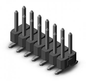
Edit: Looks like Samtec TSM-107-01-T-DV might work. Think so?

Samtec-TSM-107-01-T-DV.jpg
 
Last edited:
Trying some Samtec TSM-107-01-T-DV on Teensy3 bottom pads

Am ordering some of these today. Will let you know how they work out.
 
I've never designed a PCB before, so I'm looking for some feedback.

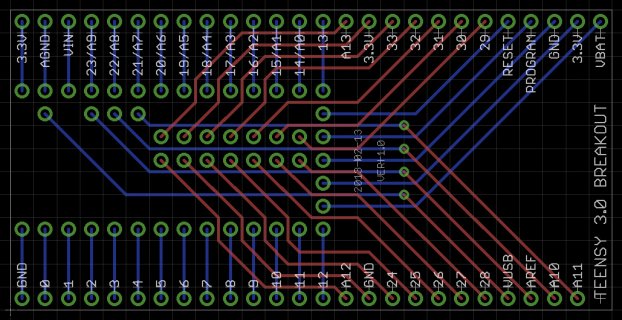
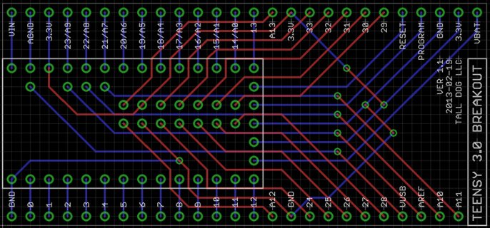
Since I've been breadboarding with the Teensy 3.0 and using a bunch of the bottom pins, I decided to try and build a breakout board for it. Also, this serves as kind of a test for mounting a Teensy 3.0 on a custom PCB in general, since I know I'll be doing this more in the future. Anyway, an image of the design is attached, and it breaks out all of the available pins to two rows that are spaced to fit well on two side-by-side (interlocked) breadboards. This also assumes use of the part listed above (Samtec TSM-107-01-T-DV) for the bottom pins.

Please let me know if you have any comments or pointers or suggestions or anything else. -Dan

Teensy 3.0 Breakout.jpg

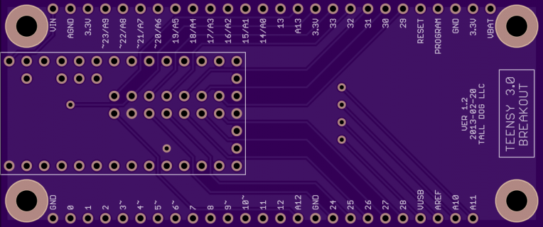
Update: Well, I finished the design after doing as much double-checking as possible. Ordered 2 of them from BatchPCB. Hope they work!

t3b.jpg
 
Last edited:
Am ordering some of these today. Will let you know how they work out.

I received mine, and they work great. Easy to solder and the alignment is perfect. It's much easier (aka basically necessary) to solder the underside header first, before the pin headers along the sides of the Teensy. In fact, I had to desolder and replace the side-pins on one Teensy in order to attach the underside pins, since my soldering iron wasn't narrow enough. -Dan
 
So loglow, are you planning to sell the PCB's? I'm sure several of us might like to buy them (though at this point, I'm not out of pins for stuff I'm thinking of, but it might be nice to have the option to buy the breakout board in the future).
 
So loglow, are you planning to sell the PCB's? I'm sure several of us might like to buy them (though at this point, I'm not out of pins for stuff I'm thinking of, but it might be nice to have the option to buy the breakout board in the future).

Once I've tested them, I'm thinking of just making them public on BatchPCB. If there's enough interest, I could get a bunch made on my own and sell them. -Dan
 
As discussed in PMs, I am definately interested too!

For what its worth, I personally would rather buy them directly from you (or your chosen supplier) so you can make a profit out of your work as well, even if that means higher (shipping)costs etc.
Not that I'm planning on buying large quantities, but all the little bits help too I guess :)
 
Yeah, I agree with ZTiK.nl, assuming the costs aren't astronomical. For me, I only tend to be interested in one off builds, and I don't contemplate buying more than a few.
 
Last edited:
Consider adding mounting holes

If I may make a tiny suggestion -- if possible have some M3 sized holes for mounting the pcb with standoffs, or for securing on wood, MDF, etc. platforms.:cool:

I don't know if it is possible to have indication of the pwm pins, touch sensor, and serial ports. I suspect you can only do so much and have it still be readable.
 
Last edited:
FWIW, just be aware that the descriptions for the 3.3V pin and the VIN pin at the top left of your board are swapped. This could lead to a bad day (i.e. burned-up Teensy 3.0).

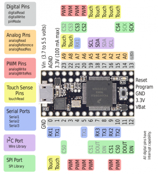
The (left to right) top pin sequence should be VIN, AGND, 3.3V, 23, etc. not 3.3V, AGND, VIN, 23, etc. as indicated by your silkscreen. See the Teensy 3.0 pinout diagram attached here for further details.

pinout5a.png

HTH (and recovering from a semi-heart attack thinking I had gotten my PCB wrong!) :)
 
Last edited:
FWIW, just be aware that the descriptions for the 3.3V pin and the VIN pin at the top left of your board are swapped

Good catch! Thanks. Gonna see about fixing that now.

Updated:
v1-1.jpg

Sent an email to BatchPCB to see about getting this fixed. At least they're cheap... :p
 
Last edited:
if possible have some M3 sized holes for mounting the pcb with standoffs, or for securing on wood, MDF, etc. platforms

I debated this, but ended up not including them because they would add a fair amount of size to the board. Likewise with the pin indicators you mentioned.

I'm gonna play around with an alternate design that incorporates some of these elements.
 
. . . worrying about users reflashing the teensy's is probably unwarranted.. providing that users aren't easily able to pull YOUR code off the device

Is there any way of protecting against this whilst still allowing for users to flash upgrade to later firmware ?
 
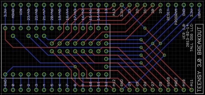
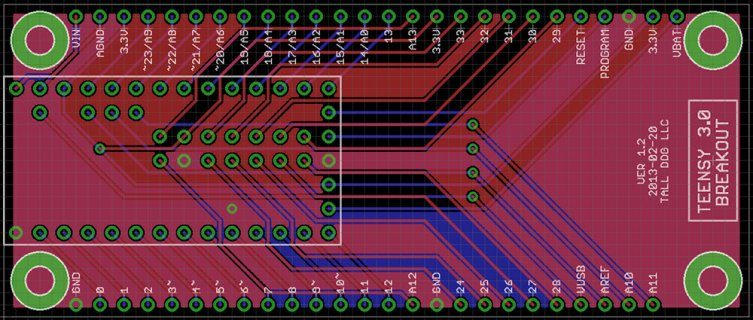
Revised PCB design.

Includes holes (0.12" for #4 screws) and PWM markers (~).

Cost is up to $12 from a little under $8 due to the size increase.

What do you think?

v1-2.jpg
i.png
 
Last edited:
Status
Not open for further replies.
Back
Top