Teensy 3.6 controlled motorfader panel

Alright I finally got one channel breadboarded and tuned the PID with what I had available on hand and it’s pretty good (quick and accurate). It’s quite a bit of components per channel, but I personally feel it’s smoother than PWM.

Here’s what the breadboard looks like:
View attachment 20417

Quick video of it action, there is no motor noise just noise from the bushings being worn out in this fader:

It can still be a tiny bit faster, I only have a 20v power supply on my test bench, this is also without having the correct op amp since this one can't produce close to its rails so moving the fader up is ever so slightly slower than going down right now. To interface this analog circuitry with a Teensy you would have to use a DAC in place of the rotary pot which I plan on using 2 AD5592R DAC/ADCs per 8 channels for a theoretical 12 bit resolution. This uses very little pins so if you wanted to you can control a lot of faders and other peripherals with just one Teensy.

I'll make a schematic of this likely tomorrow, this breadboard doesn't currently have the circuits for the low pass filters and buffers connected that would be on this in a final product.

Very interesting development! It does really seem to run smoother than the pwm drive. Two questions:
What would be required to create a setup for 16 or even 32 faders ?
How do you tune the PID parameters for the faders?
 
To create a setup for more faders you just have to repeat the circuit for however many faders you want, then interface it to the Teensy however best makes sense. Like I said for me personally I'm going to be trying it with AD5592R chips for 12 bit resolution. You need 1 ADC and 1 DAC per fader, the ADC part can be directly connected to the Teensy already and you could use PWM to emulate a DAC.

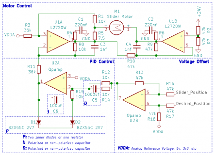
As for tuning the PID it is tuned by changing out 2 capacitor values and 2 zener diodes(or 1 resistor), P is the diodes and ID are a capacitor each. The extra capacitors and diodes you see in the video were parts I was using to test different tunings, it can be tweaked really easily you just have to swap them out and see what works best for you.

I'm working on the schematic right now so I'll label the relevant parts to change depending on your setup.
 
Here is the schematic of my current breadboard, I'm using a TL084 right now for the bottom 2 op amps, but any should work.
Screen Shot 2020-06-04 at 6.05.39 AM.png
Attached is also the KiCad project file.
Edit: Also if anyone else builds this and it doesn't seem to be working right then you have to swap your motor wires around
 

Attachments

  • MotorController.zip
    4.2 KB · Views: 190
Here is the schematic of my current breadboard, I'm using a TL084 right now for the bottom 2 op amps, but any should work.
View attachment 20488
Attached is also the KiCad project file.
Edit: Also if anyone else builds this and it doesn't seem to be working right then you have to swap your motor wires around

Thanks for providing the schematic. I'll stick to my pwm approach for now, maybe in the future when I want build another device with motor faders I'll use this approach. It would interest me what the 'big boys' like SSL are using for motor control.
When I revisit the code I plan on creating some kind of automatic PID tuning per fader to compensate for differences in friction between the faders. I think the way the faders move can be improved but as I said before for my purpose (preset recall) it works fine now. If the main purpose is slow volume fading than it makes sense to use the analog PID control, especially if the fader also carries analog signal as pwm would interfere with those signals.
 
Your other option is to just use the Motor Control part of the circuit and handle the PID and offset in the processor. The Uptown System 2000 did it this way, but each fader also had its own processor so it had enough cycles to handle the load. Of course that was decades ago so the Teensy definitely has enough processing power to handle more than one channel.

I haven’t had a look at SSL consoles, but I can tell you the Digidesign/Avid Pro Control, Control|24, and Artist Mix all use PWM control. It can easily be distinguished by the horrible performance when you group the faders and they can’t all line up correctly and in a timely fashion. Considering API bought Uptown Automation they are likely using a similar setup in their new consoles today.

I kind of like the idea of making the PID control analog as it get's rid of any loop timing problems. How do you intend to implement this physically, groups of 8? It would seem to me that using an ADC and DAC for controlling 8 faders would make a nice module with SPI interface which enables high speed communication so controlling multiple modules will not be an issue.
What kind of faders are you using? Any thoughts on what are good faders (precise control) and where to get them.
 
Depending on the application I plan on doing groups of 8 or 16, but I imagine it can easily handle more than that. I will probably make a daughter board that handles 4 channels each since my faders are pretty spread out I can’t just feasibly make one board 16 faders long.

I have Penny & Giles PGFM3000s: https://www.cw-industrialgroup.com/...bead-41e4-8915-7dd69cb2c8f1/pgfm3000_brochure
They don’t make this specific style anymore, but I imagine the new PGFM3200s are just as good if not better than these.
I’m happy with their performance considering mine were manufactured in the early 90s and they still work flawlessly today.

I haven’t made a schematic of the touch sense board yet, but it’s a little board attached to each of the faders that handles it with analog circuitry as well. It’s much more accurate than using the touch pins on a Teensy, the best part is you don’t even have to be touching ground and it’ll still be able to register skin contact correctly.

If I'm not mistaken Penny & Giles is the gold standard when it comes to (motor driven) faders:) They're probably more expensive than the N series ALPS I used but it could be worth it if one can achieve perfectly synchronous (slow) movement of multiple faders.

Glad you mentioned the touch sensing, I was wondering about that. Good to hear you already have a good solution.

Keep us posted on any developments!
 
What I don't fully understand is why you are using PID control in the first place. My experience with these motor faders (alps type) is that they have so much static and dynamic friction that inertia plays a very unimportant role. That might be different with Penny & Giles.
A very fast bang-bang control loop plus some deadband should work better?
 
In my case the PID control adds more acceleration with no dead-banding, without it the acceleration is just linear which can be slow in certain cases. It also has a little deadbanding without it because once it’s close to the set value there just isn’t enough current for the last fine movements. It’s already super smooth without PID it just helps me squeeze a little bit more accuracy and speed out of it. There’s also no need for even a fast control loop with the all analog approach, for simplicities sake I’ve just been testing it with a Teensy LC and even on that it has plenty of operating power. Considering the original 8 channel circuit was using a 16Mhz 8 bit IC from 30 years ago it’s definitely a step up.
 
What I don't fully understand is why you are using PID control in the first place. My experience with these motor faders (alps type) is that they have so much static and dynamic friction that inertia plays a very unimportant role. That might be different with Penny & Giles.
A very fast bang-bang control loop plus some deadband should work better?

Maybe if you limit the power / voltage and are ok with slower response. On the web there're some examples where people use a battery to power the fader, this will limit the current drawn. I found that with full power the faders will overshoot and oscillation will occur. For the use case of preset recall I wanted the fasted response possible so I opted for full PID control.
 
Alright I worked out the touch sense boards since I will have to redo them and make more so I can add more faders, it's quite interesting how they work and I know that the Digidesign Pro Control employs a similar method for detecting touch though it isn't all analog there.

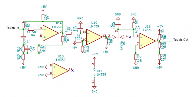
Here is the resulting schematic minus any ESD protection on the Touch_In line:
Screen Shot 2020-06-18 at 7.32.23 AM.png
Not all values have to be exact, but it's best to have a scope if you decide to change them to see what's happening.

If anyone wants to know how this works here goes, the first comparator starts by creating a square wave at about 60Khz:
Screen Shot 2020-06-18 at 7.23.36 AM.png

When you introduce skin contact you create interference in this square wave, slowing it down:
Screen Shot 2020-06-18 at 7.24.06 AM.png

From the output of the first comparator you have a simple high pass filter to filter out the 60Khz, here it is untouched:
Screen Shot 2020-06-18 at 7.25.10 AM.png Touched: Screen Shot 2020-06-18 at 7.25.34 AM.png

From that you compare it to a threshold voltage in the second comparator, that gives you a square wave only when it's touched:
Screen Shot 2020-06-18 at 7.27.16 AM.png

When that square wave goes through the diode only the positive side conducts, the other side of the diode is weakly pulled down to ground with an added capacitor to further slow down voltage changes, the square wave thus becomes this:
Screen Shot 2020-06-18 at 7.28.42 AM.png

All that's left for the last comparator to do is another threshold test and you get a nice smooth output of logic low when it's touched:
Screen Shot 2020-06-18 at 7.29.31 AM.png
 
Is it your intention to have these boards assembled somewhere or do you want to solder them yourself? It seems to me that to keep the board small one would use SMD. Are there any issues combining the touch circuit and the analog PID control on the same board, i.e. any special layout considerations?
 
There should be no issues, the Uptown System 2000 had it all on one board, likely 4 layers with a ground and power plane like the System 990. Just about the only special layout that I can see from my System 990 board is the power plane is split in half so underneath all the analog chips sits the analog reference voltage and the logic voltage is on the other half, there isn’t a separate analog ground plane though. The 24v power for the op amps just snakes between the top and bottom layers so there isn’t much consideration there, the touch sense of course just uses your normal logic supply so 3v3 for most Teensies.

I definitely plan to have them manufactured somewhere, I can do SMD soldering at least up to a tssop, but with the amount of boards I’m going to need it’s not worth doing it myself nor would it be fun. I’m still debating if I want to combine everything or not, if I do then I can just use a Teensy LC per channel to simplify things for other I/O purposes. Since it would already have a 12 bit DAC I wouldn’t need a separate chip so it is starting to sound more appealing to me. Decisions, decisions.
 
Quick followup on this while it's on my mind, while looking through the service manual for a recently acquired Lexicon 960L I got curious about the schematic for the LARC2 controller since it has motorized faders. The touch sensing part of the faders is nice and compact while probably functioning as good as the Uptown faders since it has a similar theory of operation, but instead of altering the frequency of a square wave with your bodies capacitance you are altering a low pass filter instead.

You can find the service manual here: http://www.synfo.nl/servicemanuals/Lexicon/960L_SERVICE_MANUAL.pdf
The touch sense schematic is located on page 209 or 9-61

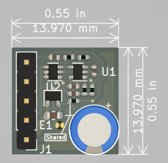
For my own sanity check I quickly made a board using the smallest SMD parts that JLPCB had in stock for their assembly service to see how small it could end up being and here's the result.
Pasted Graphic.png
The three parts marked shared are common for all eight channels so they wouldn't be repeated for subsequent channels and they are there for ESD protection.
For more than one channel, as shown here, you could use dual or quad channel ICs and save even more space.

As for the motor control circuit I would ignore that part because it just uses PWM and it looks horrible, it works for preset recall but not for automation in any sense of the word.
 
Congratulations on your acquisition! That's some seriously nice kit :)

The board certainly is small. If you plan on having a batch made, let me know as I would like to participate.
 
Hi Garrit, thanks so much for all the posts and info so far. I'd love to see more photos of the enclosure you made. Its hard to tell but it looks like a clever and somewhat custom use of vector rails. I'm also curious about if you use used kikad models for the faders. I'm using a similar yet different part number, the RSA0N11M9A0J. There is a 3d model from mouser but it just has a block box for the fader and motor. The box doesn't bother me so much as it represent the volume the fader will take up. However it doesn't have mounting holes or a representation for the slide actuator. I'm wondering you ran into this and had a workaround.
 
Hi Garrit, thanks so much for all the posts and info so far. I'd love to see more photos of the enclosure you made. Its hard to tell but it looks like a clever and somewhat custom use of vector rails. I'm also curious about if you use used kikad models for the faders. I'm using a similar yet different part number, the RSA0N11M9A0J. There is a 3d model from mouser but it just has a block box for the fader and motor. The box doesn't bother me so much as it represent the volume the fader will take up. However it doesn't have mounting holes or a representation for the slide actuator. I'm wondering you ran into this and had a workaround.

Thanks:)
There're a few pics in this thread: Zeus-Commander SP-16 MIDI step & pattern sequencer
The rails are from an old eurorack enclosure I had lying around. Only the front panels, bottom and rear are new, the rest is reused material. If I would start from scratch I probably would take a somewhat different approach but the rails allowed for flexibility while developing the device.
I created footprint for the faders myself (based on the datasheet), so no workaround just work:)
 
Alright I finally got one channel breadboarded and tuned the PID with what I had available on hand and it’s pretty good (quick and accurate). It’s quite a bit of components per channel, but I personally feel it’s smoother than PWM.

Here’s what the breadboard looks like:
View attachment 20417

Quick video of it action, there is no motor noise just noise from the bushings being worn out in this fader:

It can still be a tiny bit faster, I only have a 20v power supply on my test bench, this is also without having the correct op amp since this one can't produce close to its rails so moving the fader up is ever so slightly slower than going down right now. To interface this analog circuitry with a Teensy you would have to use a DAC in place of the rotary pot which I plan on using 2 AD5592R DAC/ADCs per 8 channels for a theoretical 12 bit resolution. This uses very little pins so if you wanted to you can control a lot of faders and other peripherals with just one Teensy.

I'll make a schematic of this likely tomorrow, this breadboard doesn't currently have the circuits for the low pass filters and buffers connected that would be on this in a final product.

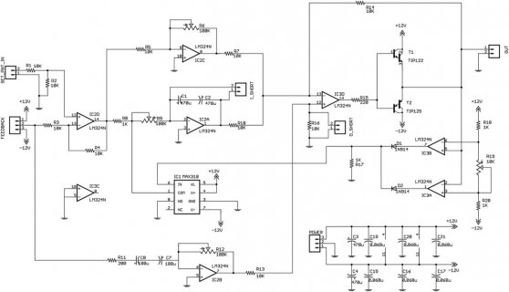
Hi , I am also working on my own motorfaders with analog PID but I am having some problems when trying to achieve both smooth slow travel and fast jumps. Fast jumps are easy but I just can't get slow smooth travel without increasing D way too much, affecting the fast jumps. Have you experienced this? I am using TKD MF-914 motorfaders with standard motors (not coreless) which I think have more friction than coreless motors. Do you know if your motorfaders have coreless motors or just standard motors? Thanks!

I am using this schematic I grabbed from the web:
NV_0205_Dahlen_Figure00.jpg
 
hello. can anyone teach me how to do this kind of project from scratch? i dunno anything about this but my goal is to do a midi controller for my Ableton with about 50 knobs and faders, with the possibility of auto faders drop like in the video too, or even what you might advise to it more too please. i am very new into this hardware installation world.
 
It could be the H Bridges or your power supply isn’t suppling enough power to the motors.


I finally ordered the parts so I’ll post a final schematic once I have all the values tuned to how I want it. My faders do not work with PWM since they have a variable torque requirement because of the position of the motors which just can’t be compensated for while using an H Bridge.

Can you elaborate a little on this statement? It jumped out to me in regards another project I've been working on.

I found this thread as I'm thinking of trying to make flying drawbars for my hammond controller. Still thinking about that.

But one shelved project I currently have is a motorized pedal steel guitar. I did get a single string proof of concept mostly working. I used a small electric motor with a drive screw and an encoder to measure its motion and I used PID and PWM with a stock H298 motor controller. And teensy of course.

The thing about string tension is that it is not at all linear. As the pitch gets higher, the torque required increases exponentially. You mentioned 'variable torque requirement' which sounded somehow similar.... So I am wondering if you have any thoughts on whether I should look into ditching pwm and trying an analog solution. I'm not sure the variable physical resistance was the problem, but I'd like a better understanding of how your analog solution overcomes the varieable torque issue.

And did you ever manufacture your fader control boards?

While I'm at it, congrats Gerrit on your sequencer, that thing is awesome! People always tell me I should patent my ideas and sell them, and can't understand why I don't want to do it (hint: tech support and sales) but I'll risk annoying you by saying the same thing ;) Great concept!

While I have yet to build the full product hopefully I can still answer your questions.

The P&G faders in question need increasing amounts of torque towards the top and bottom of its travel, this was an “intentional” feature at the time so you were less likely to ram the end stops. What that means for conventional PWM control is it’s hard to go really really slow at the ends without compensating for that. I believe that would require the PID tuning to change as it gets closer to the top and bottom of travel but I have not tested that so don’t quote me on it.

Most PWM designs that I’ve seen are speed control, the way they did it on Uptown systems is current control which obviously controls the torque of the motor regardless of speed. In Uptown systems they did this with high power op amps but it can be done with H Bridges albeit with a little more complexity, how the performance between the two compares though I don’t know.

As for the analog PID vs digital PID approach, I can’t fully speak on which is better, the “budget” Uptown 990 system is analog control while the “upgraded” 2000 system was digital and I only have experience with the former. Both systems do share the same current control part of the schematic though. In the 990 system I’m still trying to fully understand how the PID works, but I do know it works for these faders.

One advantage I can see for analog is that there is no sense of response time lag or refresh rate since it’s happening continuously in real time, one disadvantage is the tuning is basically stuck once it’s set. With digital you can always adjust the PID tunings, for the Uptown 2000 system I know you could do this in the utility program.

For you, you should probably keep the digital control since you are using encoders for your positional reading, but you may want to look into current control instead of speed control so you can adjust the torque for each string separately.

Hope that helps any and if you want some further reading here’s a great PDF with some different DC motor control methods: https://www.st.com/resource/en/appl...s-with-smart-power-ics-stmicroelectronics.pdf
 
Here is the schematic of my current breadboard, I'm using a TL084 right now for the bottom 2 op amps, but any should work.
View attachment 20488
Attached is also the KiCad project file.
Edit: Also if anyone else builds this and it doesn't seem to be working right then you have to swap your motor wires around

It's been so long since I've worked on this I went back over the schematic I drew up and of course I find an error after the fact, U2B's inputs need swapped.

I also put it into a simulator to try to "see" how it works and I believe I've got somewhat of an understanding of what is going on in terms of how the offset signal is handled, this of course differs from my original explanation in the schematic as well.

The zener diodes are not the Proportional control, they are an essential component that makes this circuit work as good as it does though, R15 is the actual Proportional control. The diodes more or less set the voltage that the PID control signal starts at, VDDA ± the breakdown voltage, what this does is preload the motor with a certain amount of current so even at the smallest of error offsets it will still immediately turn the motor. This preload also means that it's possible for this design to oscillate if you don't disable it once the offset reaches 0 since any bit of noise can trigger it, the slider will not necessarily move but with the preloaded current the oscillation with cause heat to build up in the L2720W and the motor which is never good. The original Uptown 990/2000 circuits have transistors that the controller with use to disable the motor control so this doesn't happen as well as for when touch is sensed.

With this understanding in mind I kind of have an idea on how the digital PID would be setup to replicate this and I may try to switch to that in a future project because I need every bit of PCB real estate I can get on that one.
 
With this understanding in mind I kind of have an idea on how the digital PID would be setup to replicate this and I may try to switch to that in a future project because I need every bit of PCB real estate I can get on that one.

Well, thanks for the info. I will look at that motor control pdf. I'm not an electrical engineer, so a lot of this stuff is a bit over my head... which is a good argument for digital, where I can mess around in code more without knowing precisely what I'm doing.

The problem I had with my motor control is that I need quite a bit of precision, but it was hard to move the motors by small amounts, due to torque limitations especially for higher pitches. I'll see if the pdf seems to speak to that at all (and to what extent I can track it!)

Thanks again!
 
Back
Top