Trouserhams
Member
Hi All - some help/advice would be greatly appreciated!
I've made a mistake by not paying full attention to the datasheet showing the USB pads under the 4.1 board to be USB host only and therefore unable to connect/programme through.
I've got 15 ENIG assembled PCB's that now won't function, along with full CNC'd cases for this PCB layout, and I cannot seem to get the USB connection to play ball.
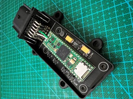
The board is currently as so;

I put the teensy round this way to keep the USB differential pair as short as possible, and used POGO pins underneath the board, but this obviously wont work due to the issue mentioned above with the host port, but this also means there is no space to use the onboard USB port either (I like a racey PCB, but this has obviously backfired here!)
I detatched the external connector pins from the PCB so the host port wasnt connected anymore, removed the original micro connector with a hot air rework wand and carefully soldered two same length wires to the external connector from the board D- and D+ connections.
The power is applied externally though the Vin pin, and I cut the trace under the board for this.
I joined the USB GND and my power supply GND for testing (eventually it will all be powered through the USB connection), but when plugging it into my PC, I get the following error from Device Manager;
I've continuity tested from the board solderpad through to the USB A connector going into my PC and cant find any issues. I'm confident the wires are only joined to their restrospective pads on the teensy.
The teeny fires up into 'Blink' when its powered through Vin, and does go into the bootloader when the button is pressed. Teensy Loader does not recognise it when it is plugged in, regardless of if the button is held whilst being plugged in.
From the above, I beleive the teensy is still alive, and I dont think I have somehow damaged it, but I also dont know why my modification hasnt worked - I appreciate USB2.0 is a higher speed protocol, but I have seen some absolute atrocities with people making FE1.1s USB hubs having no issues before, so not sure how my 20mm trace could cause complete USB protocol failure?
Any help would be greatly appreciated to resolve this mess!
I've made a mistake by not paying full attention to the datasheet showing the USB pads under the 4.1 board to be USB host only and therefore unable to connect/programme through.
I've got 15 ENIG assembled PCB's that now won't function, along with full CNC'd cases for this PCB layout, and I cannot seem to get the USB connection to play ball.
The board is currently as so;

I put the teensy round this way to keep the USB differential pair as short as possible, and used POGO pins underneath the board, but this obviously wont work due to the issue mentioned above with the host port, but this also means there is no space to use the onboard USB port either (I like a racey PCB, but this has obviously backfired here!)
I detatched the external connector pins from the PCB so the host port wasnt connected anymore, removed the original micro connector with a hot air rework wand and carefully soldered two same length wires to the external connector from the board D- and D+ connections.
The power is applied externally though the Vin pin, and I cut the trace under the board for this.
I joined the USB GND and my power supply GND for testing (eventually it will all be powered through the USB connection), but when plugging it into my PC, I get the following error from Device Manager;
Code:
Windows has stopped this device because it has reported problems. (Code 43)

A request for the USB device descriptor failed.
I've continuity tested from the board solderpad through to the USB A connector going into my PC and cant find any issues. I'm confident the wires are only joined to their restrospective pads on the teensy.
The teeny fires up into 'Blink' when its powered through Vin, and does go into the bootloader when the button is pressed. Teensy Loader does not recognise it when it is plugged in, regardless of if the button is held whilst being plugged in.
From the above, I beleive the teensy is still alive, and I dont think I have somehow damaged it, but I also dont know why my modification hasnt worked - I appreciate USB2.0 is a higher speed protocol, but I have seen some absolute atrocities with people making FE1.1s USB hubs having no issues before, so not sure how my 20mm trace could cause complete USB protocol failure?
Any help would be greatly appreciated to resolve this mess!

