Teensy 4, 4-channel audio project

rsh50

Member
Hi All,
I am new to Teensy boards and want to develop a 4-channel audio output using 2 audio boards (similar to the Teensy 3.2 tutorial from sparkfun). I want to know if there is any comprehensive guide/tutorial to achieve the same with Teensy 4.2.
Please suggest to me the links or tutorials. Thanks in advance.

Take a look at <this> thread. Also, take a look at <this> reference, particularly the description on the right-hand side of the Audio Design Tool for some additional info.

Hope that helps . . .

Mark J Culross
KD5RXT
 
The process is nearly identical to stacking 2 audio shields onto Teensy 3.2.

On the 2nd audio shield (which becomes channels 3 and 4) where to change the I2C address and cut the 2 data wires, solder the data wires to Teensy 4's pins 6 and 32. On Teensy 3.2 you would have soldered those 2 data wires to pins 30 and 15.

Documentation about which Teensy pins the quad audio uses can be found on these pages (right size panel under "Hardware")


If using Teensy 4.0, pin 32 is one of the tiny pads on the bottom side. Much easier to access pin 32 on Teensy 4.1. (you said Teensy 4.2 which doesn't exist, so answering for both 4.0 and 4.1 in hopes this helps)
 
Thank you, Paul and Mark, for your quick replies. I will try these with my teensy 4.

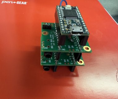
The reason why I asked for Teensy 4 is that I was working on Teensy 3.6 ( unfortunately that's the only piece of Teensy 3.6 I have as they are discontinued ) following the Sparkfun tutorial and have made all the connections and cuts as suggested.
When I uploaded the PassThroughQuad program from Arduino example I did not hear any sound on the headphones. I know it's hard to find a problem with this description. The details are as follows

1) I am using 2 audio shield revision C. (Tutorial uses revision B)
2) Capacitors from both audio shields are removed.
3) There are cuts between patches at pins 13 & 22, the center and right pad of the I2C address selector.
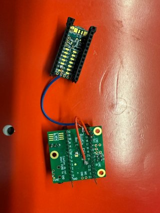
4) Used wires to make jumps as suggested.

I am posting it here because the last query answered on the tutorial was 8 years ago. So, hoping to find out what is going wrong with the connections.
I have attached my stack and the jumps image to this post.
 

Attachments

  • IMG_5012.jpeg
    IMG_5012.jpeg
    166.2 KB · Views: 52
  • IMG_5016.jpg
    IMG_5016.jpg
    188.5 KB · Views: 46
To understand why it's upside down, look at the locations of the GND pins.

1709060180642.png


1709060256118.png


For all the other pins, also compare their location on the pinout card and the pin numbers printed on those Rev C audio shields. They should all match up properly if you just flip the Teensy 3.2 over (easier said than done... but the electrons don't care as long as the soldering is solid).
 
To understand why it's upside down, look at the locations of the GND pins.

View attachment 33522


View attachment 33523

For all the other pins, also compare their location on the pinout card and the pin numbers printed on those Rev C audio shields. They should all match up properly if you just flip the Teensy 3.2 over (easier said than done... but the electrons don't care as long as the soldering is solid).
That makes more sense why its not working. I will implement the changes and try again. Thank you Paul for the quick reply.
 
I got the teensy 3.2 Quad channel working and thanks to @PaulStoffregen for his quick replies.

I want to cross-verify my teensy 4.0 quad-channel connections before I go ahead and solder them.
After reading your previous instructions and the blog picture here on Teensy 4.0. I will connect as follows
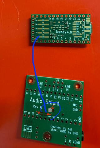
1) make cuts at data lines for pads near pin 7, pin 8, and the data line (3 pads at center) between center and right.
2) connect the center and left pads with the solder blob.
3) connect the inner pad of pin 8 with pin 6 on the audio shield
4) connect the inner pad of pin 7 with teensy 4.0 pin 32.

( The other audio shield will not be modified and will be as is.)
Then will stack the teensy 4.0 and 2 audio shields while ensuring pin numbers are aligned.

Let me know if this is all needed or if I am missing something. I have attached an image of what I described.
 

Attachments

  • teensy4-min.png
    teensy4-min.png
    1.3 MB · Views: 78
  • IMG_5050.jpeg
    IMG_5050.jpeg
    155.1 KB · Views: 51
Last edited:
I got the teensy 3.2 Quad channel working and thanks to @PaulStoffregen for his quick replies.

I want to cross-verify my teensy 4.0 quad-channel connections before I go ahead and solder them.
After reading your previous instructions and the blog picture here on Teensy 4.0. I will connect as follows
1) make cuts at data lines for pads near pin 7, pin 8, and the data line (3 pads at center) between center and right.
2) connect the center and left pads with the solder blob.
3) connect the inner pad of pin 8 with pin 6 on the audio shield
4) connect the inner pad of pin 7 with teensy 4.0 pin 32.

( The other audio shield will not be modified and will be as is.)
Then will stack the teensy 4.0 and 2 audio shields while ensuring pin numbers are aligned.

Let me know if this is all needed or if I am missing something. I have attached an image of what I described.
Hi, Did this work with the modifications you described? Did you have to remove the capacitors from the rev D boards?

Thanks in advance.
 
Back
Top