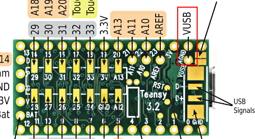
Teensy board (3.x) - Not working

Magey

Member
I broke the board's USB connection when removing a cable from a Teensy board. :(

Teensy01.png


For some context, this board was/is used to take joystick and button inputs from a simple, home made RPI based 'Arcade' machine I bought from a local guy that didn't want it any more. It all worked fine.

The reason to dismantle the equipment was to improve how the box/cabinet looked - this included a paint job, so removing the contents seemed sensible.
Anyway, so I thought it would be possible to connect to the USB contacts on bottom of the board:

Teensy_02.png


So I bought some of these:
USB_Adapter_Teensy_03.png


And did this:
USB_Adapter_Teensy_04.png


As you can see from the image, the power LED is not on. I measure 5V on the board contacts.
Seems like a dead board :(
Is there something else I can do to check/revive the board? I'd like to at least have a way to clone the program, so I can copy to new hardware.

Thanks in advance :)
 
As you can see from the image, the power LED is not on.
A Teensy 3.x does not have a power LED. The orange onboard LED is connected to pin 13. Your code can drive the LED on or off.
I measure 5V on the board contacts.
Seems like a dead board :(
Not necessarily.
Please measure on Teensy pin 3V whether you see 3V3.
Is there something else I can do to check/revive the board?
Does the board show up as a HID device or Serial device in the Device Manager (assuming your on Windows)?
Please also verify whether the D+ & D- signals are not swapped between Teensy and small USB board.
I'd like to at least have a way to clone the program, so I can copy to new hardware.
Cloning as in copying your code from the Teensy? That is impossible I'm afraid.

Paul
 
That connection looks like it ought to work. But the photo is blurry, and shot from the Teensy top side so we can't see how the wires are actually soldered. If you can share a better photo, and if it's a "simple" problem with the connection hopefully we'll be able to see.
 
Hi. Thank you very much for helping me out with this :)

A Teensy 3.x does not have a power LED. The orange onboard LED is connected to pin 13. Your code can drive the LED on or off.
oops, sorry 😳

Please measure on Teensy pin 3V whether you see 3V3.

I'm measuring 3.29v between these points :
1729957579542.png

Does the board show up as a HID device or Serial device in the Device Manager (assuming your on Windows)?
Please also verify whether the D+ & D- signals are not swapped between Teensy and small USB board.
In Device Manager I am seeing this:

1729932498486.png


1729959525529.png


It seemed like it maybe a motherboard driver issue - updating the drivers didn't help.
I tried on 2 other Win11 PC's and saw the same thing.


Data signals were connected correctly. Not my proudest moment for soldering, but the continuity between board connections seems okay with a multimeter :)
1729954912366.png
1729954818820.png


Realizing that VUSB was supposed to be connected to the pin highlighted below and not the pad, I removed the red wire from the pad to the pin hole for VUSB. This didn't change anything, but I guess that they are internally connected anyway.

1729956264698.png


Cloning as in copying your code from the Teensy? That is impossible I'm afraid.
Ahh! Ohh! Okay.

That connection looks like it ought to work. But the photo is blurry, and shot from the Teensy top side so we can't see how the wires are actually soldered. If you can share a better photo, and if it's a "simple" problem with the connection hopefully we'll be able to see.

See the pictures above + the latest soldering of the VUSB connection below from both sides :

1729959836487.png

1729960041388.png


I have tried another USB cable, with the same result. I need to confirm that these cables are not only intended for charging.

Any other suggestions?


Thanks :D
 

Attachments

  • 1729957055205.png
    1729957055205.png
    224 KB · Views: 8
Last edited:
You may want to inspect your Teensy carefully as well.

1729964363545.png


Are there perhaps shorts in the red circles?

Paul
 
Where does the bottom D+ get routed to on the Teensy? It looks like the entire pad on the top got ripped off, so if the bottom pad goes through a via to the front of it, it won't be connecting to anything.
 
Yes but how does the bottom D+ pad get routed there... This is specifically the via I'm focusing on since the pad marked in blue has been ripped from OP's board:
t32_usb_bad.png
 
Windows at least recognises something. Please swap the D+ & D- (the orange & wire) and try again. You won't hurt your PC or Teensy.

Paul
Thanks. I tried that. No change.


You may want to inspect your Teensy carefully as well.

Yeah, I did notice that and I completely agree - it doesn't look good.
Since the board was working before ripping off the USB connector, I didn't consider that to be related to the comms problem.
However, I will try to repair this too.

I checked the datasheet linked by PaulStoffregen - thanks, in it I found that one of the pins (6) seems to be related to USB :
1729980801982.png


Yes but how does the bottom D+ pad get routed there... This is specifically the via I'm focusing on since the pad marked in blue has been ripped from OP's board:
View attachment 36144
Thanks, I am also interested in this. Is there a way to bypass the broken pad/tracks?

Here is the original USB connector that was on the Teensy3.2
1729981222220.png


It is late here now, I'll have another go tomorrow. Thank you all for you help.
 
Ah, yes, this is the older Teensy 3.2 PCB where the D+ pad connects that that via to the USB connector pad, and then does underneath those 2 capacitors to reach the 33 ohm resistor.

Newer Teensy 3.2 had a different layout. Not relevant here, but mentioning because other people might later find this thread. This doesn't apply to all Teensy 3.2 boards.

For your damaged board, soldering D+ to the bottom side pad won't work because the connecting from that pad to the resistor has been destroyed on the top side. Your only hope is to solder to the tiny resistor.

Thanks.
 
Update:

Teensy_Fixed_01.png
Teensy_Fixed_02.png
Teensy_Fixed_03.png


Linked directly from D+ to R2 as you recommended and that did the trick. The board is working as expected again. 🥳

Thanks to all that helped with this :D
 
Back
Top